pin 4 0.611v and pin 8 1.3v with pins 1 and 2 jumperedWhat is the DC voltage on the power supply pins of the op-amp with the bridged pins?
Copy and paste the following list and fill in the blanks. If there is no blank space after the colon, add one between the colon and the numbers you enter. It makes it much easier to read.
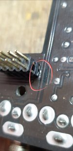
DC voltage on the 10 pin header in attached photo?
Pin 1:
Pin 2:
Pin 3:
Pin 4:
Pin 5:
Pin 6:
Pin 7:
Pin 8:
Pin 9:
Pin 10:
DC voltage on the 10 pin header in attached photo?
Pin 1:
Pin 2:
Pin 3:
Pin 4:
Pin 5:
Pin 6:
Pin 7:
Pin 8:
Pin 9:
Pin 10:
Attachments
Hello good afternoon, sorry for the delay here are the voltages
Pin 1: 4.965
Pin 2: 0.131
Pin 3: 12.88
Pin 4: 5.675
Pin 5: 12.74
Pin 6: 10.76
Pin 7: 0.629
Pin 8: 10.54
Pin 9: 9.84
Pin 10: 0.0
Pin 1: 4.965
Pin 2: 0.131
Pin 3: 12.88
Pin 4: 5.675
Pin 5: 12.74
Pin 6: 10.76
Pin 7: 0.629
Pin 8: 10.54
Pin 9: 9.84
Pin 10: 0.0

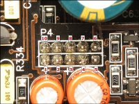
Yes. On some amps, the designation is under the resistor.
DCV on all terminals of U400?
Pin 1:
Pin 2:
Pin 3:
Pin 4:
Pin 5:
Pin 6:
Pin 7:
Pin 8:
Pin 9:
Pin 10:
Pin 11:
Pin 12:
Pin 13:
Pin 14:
DCV on all terminals of U400?
Pin 1:
Pin 2:
Pin 3:
Pin 4:
Pin 5:
Pin 6:
Pin 7:
Pin 8:
Pin 9:
Pin 10:
Pin 11:
Pin 12:
Pin 13:
Pin 14:
Pin 1: 0.9
Pin 2: 5.71
Pin 3: 1.4
Pin 4: 10.73
Pin 5: 5.74
Pin 6: 5
Pin 7: 9.45
Pin 8: 9.48
Pin 9: 5.67
Pin 10: 7.77
Pin 11: 0
Pin 12: 1.43
Pin 13: 5.22
Pin 14: 0.9
Pin 2: 5.71
Pin 3: 1.4
Pin 4: 10.73
Pin 5: 5.74
Pin 6: 5
Pin 7: 9.45
Pin 8: 9.48
Pin 9: 5.67
Pin 10: 7.77
Pin 11: 0
Pin 12: 1.43
Pin 13: 5.22
Pin 14: 0.9
Did you replace the 0.1 ohm resistor that was out of tolerance?
Did you check the FET that's driving the low-voltage transformer?
Did you check the FET that's driving the low-voltage transformer?
YesDid you replace the 0.1 ohm resistor that was out of tolerance?
Did you check the FET that's driving the low-voltage transformer?
It may work for testing but the Schmitt trigger version is likely to produce a better signal.
If there is no 5v reaching the 132, follow the circuit back, looking for an open 10 ohm resistor.
If there is no 5v reaching the 132, follow the circuit back, looking for an open 10 ohm resistor.
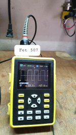
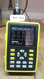
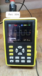
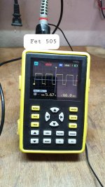
The output stage is already working but I have 23v on the output terminals between positive and negative. I notice that the fets q507 and q506 are getting hot. Could it be the high side transistors?
Are you saying that you read 23v DC when you measure with the 2 probes in the positive and negative speaker terminals?
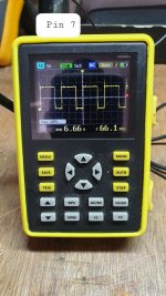
How do the gate drive signals (directly on the leg of the FET) of the FETs heating up compare to the drive signals of the corresponding FETs in the other bank of outputs?
How do the gate drive signals (directly on the leg of the FET) of the FETs heating up compare to the drive signals of the corresponding FETs in the other bank of outputs?
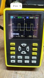
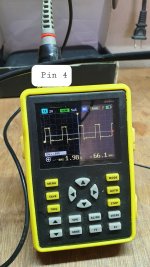
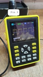
These are the gate signals in all the output fets, when I take a reading from the subwoofer terminals, placing my multimeter's negative on the power ground and with my multimeter's positive on the speaker terminals I see 52.5v on the speaker's negative and 23.75 v on speaker positive should i see 52.5v on both? I hope you understand
Attachments
- Home
- General Interest
- Car Audio
- JL Audio Slash 500/1 low ohm led