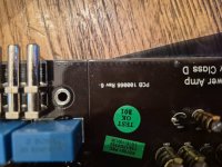
What's the resistance between the center pins of those two components?
In the 750 I posted, the FET that's in that location works with the rail voltage in an odd way (it's connected between the rail and the driver higher than rail voltage). From the traces on your board, it looks like it might have two positive rectifiers. That's why I need the resistance between the two center terminals.
Measure between the pads.
These 2 on the right appear to be rectifiers as well. That's how I got confused. So i should reinstall the mur1640cta that i just removed ?Yes the rectifiers are in the other side of the amp...View attachment 1451033
In which post did I call the 2552 a rectifier?
I need the resistance between the center pads of those two component locations.
I need the resistance between the center pads of those two component locations.
This is what I removed on my first day of working on it.
Im too confused now. Maybe i installed in a wrong location.
In post 62 and 63In which post did I call the 2552 a rectifier?
I need the resistance between the center pads of those two component locations.
I was referring to the rectifier that you previously installed.
Are you, for some reason, unable to measure the resistance between the center pads/pins of D? and D10 (the two adjacent components) on your board?
Are you, for some reason, unable to measure the resistance between the center pads/pins of D? and D10 (the two adjacent components) on your board?
I understand. I don't care about the component. I want to know about the board connections, hence the term 'pads'.
Dropped to what?
Let it go to the lowest value. what is that value?
How long did it take to get to the lowest value?
Reverse the probe positions and see how it reads?
Let it go to the lowest value. what is that value?
How long did it take to get to the lowest value?
Reverse the probe positions and see how it reads?
I was asked this....
Did you check the hi & lowoutput from the ir2010s before replacing those mosfets?
Any thoughts?
Did you check the hi & lowoutput from the ir2010s before replacing those mosfets?
Any thoughts?
That's a good question. In general, where possible (it's generally possible), you should confirm that the drive signal at the gate pads for the (not yet installed) FETs is acceptable. This is best done with a load (typically a capacitor to mimic the gate load of the FET). This is best done for all drive circuits for all FETs. This can sometimes be more difficult for self-oscillating amplifiers because you need to inject a high frequency signal to check the drive as it will be after the FETs are installed. Without injecting a signal, you can only get the highest frequency that will pass through the crossover circuit.
- Home
- General Interest
- Car Audio
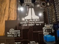
- JL Audio HD750/1 flashing green light