Decided to test my previously repaired but properly working 1000/1 in my Subaru before putting my system into my newest vehicle. Unfortunately, the Subaru only has 8 gauge power and ground wires. I didn't play the bass hard but as I turned the volume up, the amp's green power light turned off and the blue low voltage light came on. By the time I made it to the back to check the amp, it was very hot and the + power wire was so hot the sleeve started to soften. I removed the wires from the amp and it remained very hot for a few minutes until it cooled down.
When the remote lead is powered, the green light comes on and goes out as the blue light turns on. This cycle repeats until the remote wire is removed. I am getting -15v and +13.8v at the op amps and low voltage power supply. There is also regulated 5v as well as +37v on the diodes by the low voltage supply.
None of the PS FETS or outputs are shorted or give readings indicating damage. The rail voltage only gets up to +4v before shutdown occurs and the cycle repeats. During this testing, the amp's current draw is so high that the red+ power wire moves as the amp attempts to turn on. This amp has IRF3709Z with 22ohm resistors in the power supply that were working well for a few months
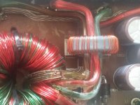
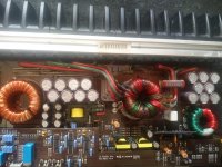
I am uncertain if the toroid is damaged as the rubber coating had somewhat melted during this incident. I am posting some pics.
When the remote lead is powered, the green light comes on and goes out as the blue light turns on. This cycle repeats until the remote wire is removed. I am getting -15v and +13.8v at the op amps and low voltage power supply. There is also regulated 5v as well as +37v on the diodes by the low voltage supply.
None of the PS FETS or outputs are shorted or give readings indicating damage. The rail voltage only gets up to +4v before shutdown occurs and the cycle repeats. During this testing, the amp's current draw is so high that the red+ power wire moves as the amp attempts to turn on. This amp has IRF3709Z with 22ohm resistors in the power supply that were working well for a few months
I am uncertain if the toroid is damaged as the rubber coating had somewhat melted during this incident. I am posting some pics.
Attachments
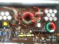
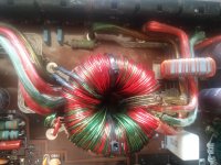

With your fingernail, can you scrape away the enamel on the large green bundle of windings coming over the top of the transformer?
Kinda yes and no. The enamel/paint isn't just scraping off with my fingernail any more than is already removed. The copper is exposed in that area but nowhere else.
It's likely shorted, then. Push inward on the winding to separate it from the other windings. Slide an insulator (plastic, cardboard, paper...) as far as you can between the green and other windings. Does that allow it to power up?
Tried that and it still doesn't power up. Green light for a half a second, blue light for half a second...
Tried twisting and turning and bending, the Transformer and its leads with no change.
Tried twisting and turning and bending, the Transformer and its leads with no change.
So is a shorted Transformer the only reason this amp will no longer power up?
I assume from other related posts, if the transformer is defective, then the only fix is JLs flat rate repair?
I assume from other related posts, if the transformer is defective, then the only fix is JLs flat rate repair?
Just scanned the list of amplifiers that JL Audio will repair, and the 1000/1v1 is not on the list. Also, I do not possess the original sales receipt. Looks like I will either have to attempt the transformer repair or sell the amp for parts if it is unrepairable...Can't believe the amplifier self-destructed/was destroyed so easily...
Is there 100% certainty that the transformer is what is causing the amplifier to not power up?
Is there 100% certainty that the transformer is what is causing the amplifier to not power up?
If the amp doesn't draw any current with only B+ and ground connected, remove the two 22uf caps next to the driver transformers. Will the amp power up without going into protect or drawing excessive current with those removed?
With the two 22uf capacitors removed, there is no protection light and the green light illuminates continuously. There is no excessive current draw with or without remote power.
Power up the amp and then remove remote after a few seconds, monitoring the gate drive (with your scope) from when the remote is removed. Do you have a good drive signal on all outputs?
The drive will remain for only about 10-15 seconds after removing remote.
The drive will remain for only about 10-15 seconds after removing remote.
On the 12 ps FETS that have their source leg connected to the small toroid just behind there is absolutely no response to remote power/no gate drive voltage.
On the 12 ps FETS that have their source leg connected to the large transformer there is some form of action. With the black probe on the ground terminal and the red probe on the gate leg, there is approximately +.75v. If the red probe is removed and reconnected the meter reads around 2-3v which then diminishes down to +0.6v.
On those same FETS that had a reading, if I probe them with just B+ and Ground connected, I read 4v on the drain leg and gate leg which diminishes as soon as the probe is applied.
Got different readings on the 8 output gates:
Q500 5.6V jumps to 2.5v at remote power application
Q501 5.6V jumps to 2.5v at remote power application
Q502 2.2V jumps to 2.5v at remote power application Q503 2.2V jumps to 2.5v at remote power application Q504 0.12V
Q505 1.55V
Q506 0.06V
Q507 0.91V
Q500 5.6V jumps to 2.5v at remote power application
Q501 5.6V jumps to 2.5v at remote power application
Q502 2.2V jumps to 2.5v at remote power application Q503 2.2V jumps to 2.5v at remote power application Q504 0.12V
Q505 1.55V
Q506 0.06V
Q507 0.91V
Just discovered Q504 shorted on all 3 legs. I don't recall any shorted outputs when after the incident occurred but I may have been flustered and did something incorrectly.
Should I remove the outputs and recheck gate signal, or should I replace the outputs.
Do I need to replace all 8, the 4 on that side, or just the 2 that are paralled
Should I remove the outputs and recheck gate signal, or should I replace the outputs.
Do I need to replace all 8, the 4 on that side, or just the 2 that are paralled
For now, remove the shorted FET and re-check the drive signals.
I would replace the four that are working together.
I would replace the four that are working together.
Removed the shorted FET at Q504 and retested.
Q500/Q501 5.6V
Q502/Q503 2.2V
Q504/Q505 6.7V
Q506 0.06V
Q507 0.91V
The mismatched readings on 506 and 507 caused me to investigate further and I discovered that the gate of these two had Ground on them. I traced the gate circuit back to U502, a TC4420E IC mounted just in front of the output driver board. This IC has pins 4, 6, 7 and 8 shorted together. I assume no further testing can be done until this part is replaced.
My questions are:
1) Could this shorted IC and output FET be responsible for the amplifier not powering up, or is there still a chance of the amplifier having catastrophic transformer damage? I am accustomed to JL Audio amplifiers showing the low ohm light when the outputs are shorted so I don't know under what circumstances the low voltage light illuminates...
2) If there is a chance of the amplifier being repairable I would like to order all possible needed parts at the same time. Could you possibly suggest what other parts should be ordered?
I had repaired this amplifier as per your recommendations earlier this year. It was repaired with, and worked flawlessly for months with IRF3709Z FETS and 22 ohm gate resistors with IRFB31N20D outputs.
- Status
- Not open for further replies.
- Home
- General Interest
- Car Audio
- JL Audio 1000/1v1 low voltage light