Would you happen to know what should check next since both thoose resistors i jus put in burn up within 2 secs
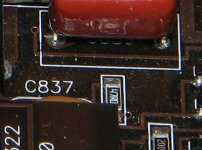
The only thing connected to both of those resistors is the transistor standing on the board right next to the resistors.
Yeah thats it its shorted from Legs 1-3
Is there anything i can use for a sub so i can est somemore ??
Orginal is a FQP30N60L
Is there anything i can use for a sub so i can est somemore ??
Orginal is a FQP30N60L
30N06L, not 30N60L.
This is a 'logic level' FET. The drive circuit doesn't have enough voltage to properly drive a standard FET. You may be able to use something like a 3205 for testing to see if there are other problems but you'll need to get the proper transistor for long term use.
This is a 'logic level' FET. The drive circuit doesn't have enough voltage to properly drive a standard FET. You may be able to use something like a 3205 for testing to see if there are other problems but you'll need to get the proper transistor for long term use.
Ok i orderd the Correct transistor.. (FQP30N06L)
The 47 ohm resistor connected to Leg 1 of that transistor both of the pads burnt off the board...
Instead of an SMD resistor going back in that location I was gonna use a leaded resistor to i can solder right to leg 1 and the other side i can drill a small hole thru the board and solder it from the under side of the board..
Would a 1/4 watt 47 ohm resistor work or should i use a 1/2 watt ?
Also the 0.1 ohm resistor is a 2 watt ??
3rd question is With the FQP30N06L , 0.1 ohm and the 47 ohm resistor all being bad would that cause the low ohms light ?
A 1/8w resistor would be sufficient. A 1/4w will work.
I'd suggest that you solder to the pad and fix the resistor down with a suitable fixative/adhesive. I think these are only 2-layer boards but I'm not sure. Unless you can see light all around the pad and there is no trace/copper on the other side, it's not safe to drill.
Match the size when ordering.
I can't help with the 3rd question. I've never had an amp with this failure that I looked at the LEDs.
Yes this is a double sided board..
Both pads are missing..
I can drill thru the board on 1 side of the resistor and connect it from underneath the board and the connect the other side of the resistor to Leg 1 from the top side of the board and use some silicone to keep the resistor in place..
I guess i wait til friday or saturday to test this amp somemore since thats when the parts come in..
Just scrape the trace and lay the leg of the resistor along the trace. I think it's a mistake to drill through this board. If you do and open or short internal layers (this could be a 3-layer board), the amp may not be repairable.
I put the parts in this amp .. I had sound for a min now no sound at all..
On the power supply fets I only get 13.8 volts on the middle leg ..
The gate leg shows 0 volts..
I also have no rail voltage at any of the outputs..
Any ideas on where to check??
On the power supply fets I only get 13.8 volts on the middle leg ..
The gate leg shows 0 volts..
I also have no rail voltage at any of the outputs..
Any ideas on where to check??
This supply isn't like most amps. The drive circuit is like an MTX amp. The gate terminals may not have any DC when driven. Do you have any oscillation on any power supply components?
If the ground pin and pins 13 and 15 are straight clean lines, post the DC voltage on all pins of that IC.
Pin 1: 0.00
Pin 2: 3.66
Pin 3: 0.19
Pin 4: 0.11
Pin 5: 1.43
Pin 6: 2.40
Pin 7: 1.42
Pin 8: 2.62
Pin 9: 4.00
Pin 10: 0.00
Pin 11: 1.01
Pin 12: 0.00
Pin 13: 5.53
Pin 14: 0.00
Pin 15: 5.54
Pin 16: 3.67
Pin 2: 3.66
Pin 3: 0.19
Pin 4: 0.11
Pin 5: 1.43
Pin 6: 2.40
Pin 7: 1.42
Pin 8: 2.62
Pin 9: 4.00
Pin 10: 0.00
Pin 11: 1.01
Pin 12: 0.00
Pin 13: 5.53
Pin 14: 0.00
Pin 15: 5.54
Pin 16: 3.67
- Status
- Not open for further replies.
- Home
- General Interest
- Car Audio
- JL Audio 1000/1