I think 8,9,10 are turn on control/low voltage protection. I think pin 10 may be your problem.
Compare the voltage on that pin when it does/doesn't come on.
Is the signal sense switch set the OFF position. These switches cause problems but generally the type of intermittent powering up.
Compare the voltage on that pin when it does/doesn't come on.
Is the signal sense switch set the OFF position. These switches cause problems but generally the type of intermittent powering up.
Just tried it after sitting overnight, first application of power nothing booted up. Switched off the bench supply for 10 seconds and switched it back on again, both main and standby spring to life without remote application. Pin 10 was the same both times, it seems to hover around 9-10 volts and the signal sensing switch position doesn’t affect it.
No, but I noticed just now that when the standby circuit isn’t powered (bench supply on, remote not connected) pins 12&13 on the 324 have nothing on them. If the #4 opamp is supposed to work like the #1 opamp, then there ought to be voltage on the inverting input. Maybe it simply has a hair trigger, because there’s nothing there for the remote circuit to overcome? Still investigating....
It’s pretty clean, believe me I’ve spent days scrutinizing this thing under glass and strong light lol.
So I was just probing pin 12 and the standby supply was off, when suddenly the voltage disappeared and the amp came to life. In other words, I caught it in the act so to speak. I think what’s happening is its coming on because of this sudden drop in sensing voltage, so next question is what parts supply that voltage to pin 12? My eyes already hurt from staring at this thing lol.
So I was just probing pin 12 and the standby supply was off, when suddenly the voltage disappeared and the amp came to life. In other words, I caught it in the act so to speak. I think what’s happening is its coming on because of this sudden drop in sensing voltage, so next question is what parts supply that voltage to pin 12? My eyes already hurt from staring at this thing lol.
Dammit, you beat me to it. I was just probing the board and pressing in a certain spot makes it turn on and off, gotta be a bum joint somewhere. I’m gonna solder the p!ss (really, p!ss is censored? lol) out of every component on here real quick. See if that fixes it.
And yes the input caps all exploded, but the boards have been scrubbed multiple times and new parts are in. I really don’t think I’m dealing with electrolyte, this seems to be a mechanical failure.
And yes the input caps all exploded, but the boards have been scrubbed multiple times and new parts are in. I really don’t think I’m dealing with electrolyte, this seems to be a mechanical failure.
Remote issue appears to be solved at last!
I studied the pre board one last time before going hog wild with the soldering tool, but still couldn’t find anything that looked cracked. Must have been something though, cause after reflowing everything on the right side of the board the problem seems to have disappeared. Yay!
I went for broke and put the rectifier back in and turned it on- DC on the output and the duty cycle on the FETs is full on. I recall I had another amp that did this, didn’t it wind up being more bad solder on the main board near the ramp generator?
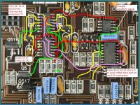
Found the ramp generator and comparator chips, they are U404 (NE555) and U407 (LM319) respectively. Pin 6 of U404 has a nice ramp coming out of it, which is then fed to pin 5 (inverting input of comparator #1) of U407. This means the audio input must be on pin 4 (comparator #1 non-inverting input), correct?
I was asking because with no outputs, the feedback loop would be broken and the 100% duty cycle could be normal.
You need to find the servo op-amp used for feedback and bridge its output and inverting input to see if the duty cycle went to 50%. The attached is from a 500. I don't know if it will help since the 250 has a different layout.
You need to find the servo op-amp used for feedback and bridge its output and inverting input to see if the duty cycle went to 50%. The attached is from a 500. I don't know if it will help since the 250 has a different layout.
Attachments
Servo is indeed U408, an NJM2068, and it turns out that shorting the output of the #2 opamp (pin 7 to ground) causes the bridge to balance itself like you’d expect. There’s not much going on with the inverting (pin 6, 72mv) and non-inverting (pin 5, 0v) pins of that side of the chip, so is it safe to assume it’s shorted?
- Status
- This old topic is closed. If you want to reopen this topic, contact a moderator using the "Report Post" button.
- Home
- General Interest
- Car Audio
- JL 250/1v2 factory defect