Clearly, such a system is not "real-time".
Yet they promote it for such applications as professional recording and mixing desks.
The specs on their web site seem exemplary, but they don't like to confuse matters with too much extraneous information.
A question: if a hypothetical DAC with a simple reclocking scheme were driven with a stream of almost exactly the 'right' frequency (even with some jitter), could very good results be obtained, while with a stream of a different sample rate things might not turn out quite so well?
Hi,
The log frequency scale results and measured unweighted output noise?
BTW, the equations are in the public domain, you may look them up as you like.
Ciao T
The equations?
The log frequency scale results and measured unweighted output noise?
BTW, the equations are in the public domain, you may look them up as you like.
Ciao T
Hi,
Well, zero latency is not needed for these...
You can get extensive datasheets from ESS, as long as you sign these drakonian NDA's and they will probably send a Terminator 3000 back in time to kill you (or worse, get american lawyers on your a.s.s.) if you say anything.
BTW, I assume the Datasheets are extensive, I would not know and if I did know I could not possibly tell you.
I have done this with practical DAC's.
And the answer is: fine for noisy music Tekkno, Death Metal etc.), heck on solo Piano (sounds like LP clicks) on the right sample rate, unlistenable on others.
You are better off using the highest possible clock oscillator for reclocking and not bothering with with "getting close". It creates a cyclic jitter at a very high PP Value and very high frequency, with some dependence on source jitter.
It sounds different. It measures extremely horrible (either way).
Ciao T
Yet they promote it for such applications as professional recording and mixing desks.
Well, zero latency is not needed for these...
The specs on their web site seem exemplary, but they don't like to confuse matters with too much extraneous information.
You can get extensive datasheets from ESS, as long as you sign these drakonian NDA's and they will probably send a Terminator 3000 back in time to kill you (or worse, get american lawyers on your a.s.s.) if you say anything.
BTW, I assume the Datasheets are extensive, I would not know and if I did know I could not possibly tell you.
A question: if a hypothetical DAC with a simple reclocking scheme were driven with a stream of almost exactly the 'right' frequency (even with some jitter), could very good results be obtained, while with a stream of a different sample rate things might not turn out quite so well?
I have done this with practical DAC's.
And the answer is: fine for noisy music Tekkno, Death Metal etc.), heck on solo Piano (sounds like LP clicks) on the right sample rate, unlistenable on others.
You are better off using the highest possible clock oscillator for reclocking and not bothering with with "getting close". It creates a cyclic jitter at a very high PP Value and very high frequency, with some dependence on source jitter.
It sounds different. It measures extremely horrible (either way).
Ciao T
OK, so you basically made that number up? Or was it calculated somehow? We can move on once I understand your assertion.
Sy,
The measurements in a reasonable format please, so we can move on.
Otherwise, -105dBfs...
Ciao T
OK, so you basically made that number up? Or was it calculated somehow? We can move on once I understand your assertion.
The measurements in a reasonable format please, so we can move on.
Otherwise, -105dBfs...
Ciao T
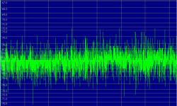
OK, so the numbers are made up. And my point remains, since noise inside a computer is mostly high frequency, which I considerately show in great detail.
With that, I'll bow out until someone wants to have an honest discussion.
With that, I'll bow out until someone wants to have an honest discussion.
Sy,
The number (there is only one) is based on a reading of noise estimated from your measurements.
You are saying noise in the PC (to be precise on the PSU) is HF?So you have actually measured it?
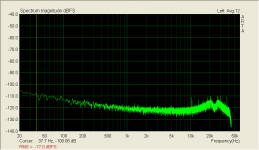
Your measurement shows a level of around -105dB for LF noise (frequency is hard to tell), You can work out what SNR and hence resolution this gives.
Oh come on, you post a measurement result, deliberately shown in a non-standard way to obscure low frequency noise. I told you what that noise level is. If you don't like it, ask your money back.
Ciao T
OK, so the numbers are made up.
The number (there is only one) is based on a reading of noise estimated from your measurements.
And my point remains, since noise inside a computer is mostly high frequency, which I considerately show in great detail.
You are saying noise in the PC (to be precise on the PSU) is HF?So you have actually measured it?
Your measurement shows a level of around -105dB for LF noise (frequency is hard to tell), You can work out what SNR and hence resolution this gives.
With that, I'll bow out until someone wants to have an honest discussion.
Oh come on, you post a measurement result, deliberately shown in a non-standard way to obscure low frequency noise. I told you what that noise level is. If you don't like it, ask your money back.
Ciao T
Are you sure you're using the correct equations for that?
Signal-to-noise ratio - Wikipedia, the free encyclopedia

That makes 16 bit to have a max DR/SNR of 96dB. The level of 105dB makes some 17.5bit. The best DAC's followed by top-shelf OpAmps go to 20-21 bit accuracy...
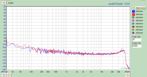
Why don't you show a log frequency scale result so we can have a good look, instead of having to guess.
AKAIK, that is the way the software displays it. It can just do other units, not other scales. For comparison - below you will find my built-in Realtek soundcard on my desktop computer. The mixer is set for line in, full on. I scaled both the same for a reasonable comparison.
Attachments
Well, zero latency is not needed for these...
Well, Wikipedia on propagation delays in mixing desks says:
Digital mixers have an unavoidable amount of latency or propagation delay, ranging from 1.5 ms to as much as 10 ms, depending on the model of digital mixer and what functions are engaged. This small amount of delay isn't a problem for loudspeakers aimed at the audience or even monitor wedges aimed at the artist, but can be disorienting and unpleasant for IEMs (In ear monitors) where the artist hears their voice acoustically in their head and electronically amplified in their ears but delayed by a couple of milliseconds.
Every analog to digital conversion and digital to analog conversion within a digital mixer entails propagation delay. Audio inserts to favorite external analog processors make for almost double the usual delay. Further delay can be traced to format conversions such as from ADAT to AES3 and from normal digital signal processing steps.
Within a digital mixer there can be differing amounts of latency, depending on the routing and on how much DSP is in use. Assigning a signal to two parallel paths with significantly different processing on each path can result in extreme comb filtering when recombined. Some digital mixers incorporate internal methods of latency correction so that such problems are avoided.
I'm guessing that real time operation is, in fact, a requirement for a typical DAC in a typical mixing desk. Or, putting it another way, a latency of more than a couple of milliseconds would not make it a great contender when designing the desk!

Pano: Noise floor and signal to noise are very different animals. Same with resolution. When we mix them up, it tends to obscure the basic points. -105dB unweighted signal to noise is quite acceptable in audio gear, far better than most audiophile gear manages. Resolution is quite a bit better than that. The highest noise component is a 120Hz spike (which may originate externally, don't know, don't care) at -120dBFS. PCI cards apparently do not have to be as noisy as people worry about.
Your cheap soundcard's S/N is probably working at the edge of audibility- if it were a high end phono preamp, that number would be impressive!
Your cheap soundcard's S/N is probably working at the edge of audibility- if it were a high end phono preamp, that number would be impressive!
Yes, a cumulative S/N of -77dB is not bad for analog gear. I suppose that most of that noise is from the analog section.
Still handy for spectrum analysis, tho.
Still handy for spectrum analysis, tho.
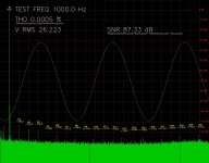
I did a test on my M Audio 2496 sound card a while ago. I was intending to measure a power amplifier's performance but also did a loopback test with a 16 bit 44.1kHz 1kHz sine wave. I read somewhere that distortion is usually lower with sound cards at reduced output amplitude and I certainly found that 50% gave me significantly lower distortion, although it must have reduced my signal to noise ratio, too.
Homebrew software, so not presenting the plot in the 'official' manner I expect, but I believe the displayed figures are correct. Based on a large FFT averaged many times (I can't say how large and how many at the moment!) and a simple raised cosine window. Using 'several' bins on either side of each harmonic to accumulate the harmonic energy. Using everything minus the THD components to calculate the SNR relative to the fundamental.
The loopback cable wasn't cotton covered silver I'm afraid, so no doubt a heavy performance penalty there.
(Forget the VRMS figure - it was for the power amplifier output after an attenuator not used for this test)
Attachments
Last edited:
87.33dB - looks entirely reasonable for SNR.
<edit> Caveat - remember that's an average SNR over the whole acquisition period.
<edit> Caveat - remember that's an average SNR over the whole acquisition period.
I'm still fascinated by this ESS DAC that appears to have it all: the best THD and noise specs in the industry, oblivious to incoming sample rate, and not even slightly affected by source jitter - using this DAC, jitter does, indeed, appear to be a "non-issue".
Thorsten, you said it could not perform like that and be "real time". Well, Googling around, I find that the chip's designer saying that it has a latency of about 833us - obviously FIFOs and DPLLs/'frequency locked loops' are for losers!
DIYHiFi.org • View topic - ESS Sabre DAC Opinions?
Then from http://www.esstech.com/PDF/sabrewp.pdf:
Figure 3 shows the DAC being completely unaffected by '2ns random jitter' while a "competitor" suffers badly. So how do you eliminate source jitter without any buffering..? I can't get my head around it.
The publicly available data sheets and test results are obviously just meant to be tokens of the conventional documentation that other manufacturers provide, and you have to sign an NDA before being given anything very technical. Despite (because of?) this, the DACs are widely acknowledged as the best in the world. As a result, everyone expects these DACs to sound great, and they do, apparently.
Here's the manual of a commercial DAC based on one of these devices, with seemingly comprehensive test results:
http://www.resonessencelabs.com/invicta/InvictaUserGuideILB.pdf
Purely out of intellectual curiosity, can anyone suggest how this miracle works? We're talking about a designer who has come up with something that seemingly blows the efforts of massive corporations like TI and Analog Devices out of the water, with other big names queuing up to use these devices. Surely you FIFO people must be a little bit curious?!
Thorsten, you said it could not perform like that and be "real time". Well, Googling around, I find that the chip's designer saying that it has a latency of about 833us - obviously FIFOs and DPLLs/'frequency locked loops' are for losers!
I just wanted to point of a couple things, just for the sake of clarity. Obviously I cant say Exactly how we did the ASRC other than that which is written into the patent. But basically it doesn't use any buffering or FIFO method. THe latency throught the whole chip is 833uS at 44.1kHz sample rate, including the ASRC blob. The ASRC does have to lock onto the input rate, I just did it with a bandwidth of 0.1Hz.
DIYHiFi.org • View topic - ESS Sabre DAC Opinions?
Then from http://www.esstech.com/PDF/sabrewp.pdf:
Rather than trying to lock a PLL to the data rate of this interface signal, the Sabre DSP uses the arrival time of the data as a gating signal for the first part of the processing. Specifically, we now need to apply a filter to the digital data – we must remove the image that will be created when we up-sample the data to our much higher clock rate. This filter involves a number of cycles of the DSP. One desirable consequence of this method is that the over-sampling filter time constant tracks the data rate. The data we have after this process is, of course, mathematically correct, but if we use this data in the higher clock domain we will have a great deal of noise, since as soon as we try to sample the data we must decide at which edge of our high speed clock this data is to be used. That choice is never correct – this sample delivered from the interface is supposed to be at some point between our high speed clock edges. The problem then is this: we have the data stripped off the transport medium – the data is mathematically correct but we don’t know where in time this data is supposed to be, and even if we did we cannot snap it to our high speed clock because that represents a quantization in time and hence noise. The conventional solution is well known: first a digital PLL is used to remove the jitter of the incoming data (since it will suffer from jitter in the transport clock) and then a poly-phase filter is employed to rate-convert the signal8 into the new clock domain. These kinds of sample rate converters work well but they are limited to certain ranges of operation (they have a limited ratio of rate conversion – typically about 8:1) and a DNR less than that in the digital data itself. The Sabre DAC rate converter has two advantages compared to the poly-phase filter approach and is described in great detail in the pending patent. Firstly the rate conversion is unlimited – allowing the Sabre to always achieve a conversion into its exceptionally high clock rate (as much as 40Mhz) from as little as 4Khz in one step; and secondly, the process is essentially perfect to the bit level – the output DNR exceeds 175dB and the THD is correspondingly high. As well as sample rate conversion the Sabre has a proprietary jitter reduction circuit that operates with the rate converter and is able to achieve a 100% jitter rejection. These two steps: jitter rejection and rate conversion; are able to take the “burst” mode over-sampled filter output into the precisely correct clock edge of the high speed clock. Audio data from all sources is now in the high speed clock domain and sent to the modulator.
Figure 3 shows the DAC being completely unaffected by '2ns random jitter' while a "competitor" suffers badly. So how do you eliminate source jitter without any buffering..? I can't get my head around it.
The publicly available data sheets and test results are obviously just meant to be tokens of the conventional documentation that other manufacturers provide, and you have to sign an NDA before being given anything very technical. Despite (because of?) this, the DACs are widely acknowledged as the best in the world. As a result, everyone expects these DACs to sound great, and they do, apparently.
Here's the manual of a commercial DAC based on one of these devices, with seemingly comprehensive test results:
http://www.resonessencelabs.com/invicta/InvictaUserGuideILB.pdf
Purely out of intellectual curiosity, can anyone suggest how this miracle works? We're talking about a designer who has come up with something that seemingly blows the efforts of massive corporations like TI and Analog Devices out of the water, with other big names queuing up to use these devices. Surely you FIFO people must be a little bit curious?!
Last edited:
Here's how I think it works (I may be mistaken of course).
Part 1:
Like any other delta-sigma, this DAC oversamples the input stream to a very high sample rate. This high sample rate is synchronous to the input signal (ie, jittery). It has to be synchronous to the input signal, since the oversampling filter must operate on the input sample rate if we want the filter coefficients to actually mean something (DSP basics) :
Apparently, it uses some clever DSP tricks too :
So apparently they didn't do it with a textbook polyphase filter, and their stuff gives better characteristics (less rounding error, less distortion, etc).
It also has a very fast output sample rate (up to 40 MHz) relative to other sigma-deltas, and an output converter with a decent number of bits. So, the output D/A converter can encode a lot more information than some other DACs.
Part 2:
Anyway, say we have oversampled the input signal to 40 MHz. This signal's sample clock is still synchronous with the input clock, therefore it is still jittery. Sabre DAC applies ASRC then.
How does a standard ASRC work ?
- have a low jitter master clock which will control the output samples timing
- compute the arrival times of the input samples relative to this master clock
- apply some filtering (ie, lowpass with cutoff below 1 Hz) to remove jitter
From this, it can compute at which position in time (relative to the master clock) each input sample is supposed to be, with jitter removed.
Output samples don't line up with input samples since the two sample rates are not equal and synchronous.
But with this information it also can compute the position in time of each output sample relative to the input sample stream.
It then computes the mathematical equivalent of :
1- oversampling the input signal to a very high frequency
2- picking the value of this signal at the exact time that corresponds to an output sample
3- and bring this back to the output sample rate
I say "mathematical equivalent" because the oversampling is actually not done, instead a FIR filter is done on the input samples which yields an output sample, and the coefficients determine the timing of point 2. The coefficients need to be adjusted in real time according to the timing difference between input and output samples. This is in fact pretty difficult to do and a major source of problems with ASRC...
From what I've seen, ASRCs have tables of coefficients for FIR filters, each one doing the above operation for a fixed time difference between input and output samples, and the fine delay adjustments are done by linear interpolation between those.
The ESS DAC does it in a much simpler way.
- It knows at which point (in the oversampled input sample stream) each output sample should correspond (output sample here is 40 MHz output DAC samples)
- since clocks are not synchronous, there is no exact sample to sample relation
- therefore it uses simple linear interpolation between successive oversampled input samples to "connect the dots" and know what value the output DAC should output at the master clock edges.
It is basically the same as an ASRC, with all the DSP removed (and all the potentially nasty rounding errors etc).
The output samples are then sent to the D-S modulator and to the actual DAC, both work on the master clock.
It's extremely simple and clever.
Part 1:
Like any other delta-sigma, this DAC oversamples the input stream to a very high sample rate. This high sample rate is synchronous to the input signal (ie, jittery). It has to be synchronous to the input signal, since the oversampling filter must operate on the input sample rate if we want the filter coefficients to actually mean something (DSP basics) :
we now need to apply a filter to the digital data – we must remove the image that will be created when we up-sample the data to our much higher clock rate. This filter involves a number of cycles of the DSP. One desirable consequence of this method is that the over-sampling filter time constant tracks the data rate.
Apparently, it uses some clever DSP tricks too :
The Sabre DAC rate converter has two advantages compared to the poly-phase filter approach and is described in great detail in the pending patent. Firstly the rate conversion is unlimited – allowing the Sabre to always achieve a conversion into its exceptionally high clock rate (as much as 40Mhz) from as little as 4Khz in one step; and secondly, the process is essentially perfect to the bit level – the output DNR exceeds 175dB and the THD is correspondingly high
So apparently they didn't do it with a textbook polyphase filter, and their stuff gives better characteristics (less rounding error, less distortion, etc).
It also has a very fast output sample rate (up to 40 MHz) relative to other sigma-deltas, and an output converter with a decent number of bits. So, the output D/A converter can encode a lot more information than some other DACs.
Part 2:
Anyway, say we have oversampled the input signal to 40 MHz. This signal's sample clock is still synchronous with the input clock, therefore it is still jittery. Sabre DAC applies ASRC then.
How does a standard ASRC work ?
- have a low jitter master clock which will control the output samples timing
- compute the arrival times of the input samples relative to this master clock
- apply some filtering (ie, lowpass with cutoff below 1 Hz) to remove jitter
From this, it can compute at which position in time (relative to the master clock) each input sample is supposed to be, with jitter removed.
Output samples don't line up with input samples since the two sample rates are not equal and synchronous.
The problem then is this: we have the data stripped off the transport medium – the data is mathematically correct but we don’t know where in time this data is supposed to be, and even if we did we cannot snap it to our high speed clock because that represents a quantization in time and hence noise.
But with this information it also can compute the position in time of each output sample relative to the input sample stream.
It then computes the mathematical equivalent of :
1- oversampling the input signal to a very high frequency
2- picking the value of this signal at the exact time that corresponds to an output sample
3- and bring this back to the output sample rate
I say "mathematical equivalent" because the oversampling is actually not done, instead a FIR filter is done on the input samples which yields an output sample, and the coefficients determine the timing of point 2. The coefficients need to be adjusted in real time according to the timing difference between input and output samples. This is in fact pretty difficult to do and a major source of problems with ASRC...
The conventional solution is well known: first a digital PLL is used to remove the jitter of the incoming data (since it will suffer from jitter in the transport clock) and then a poly-phase filter is employed to rate-convert the signal8 into the new clock domain. These kinds of sample rate converters work well but they are limited to certain ranges of operation (they have a limited ratio of rate conversion – typically about 8:1) and a DNR less than that in the digital data itself.
From what I've seen, ASRCs have tables of coefficients for FIR filters, each one doing the above operation for a fixed time difference between input and output samples, and the fine delay adjustments are done by linear interpolation between those.
The ESS DAC does it in a much simpler way.
- It knows at which point (in the oversampled input sample stream) each output sample should correspond (output sample here is 40 MHz output DAC samples)
- since clocks are not synchronous, there is no exact sample to sample relation
- therefore it uses simple linear interpolation between successive oversampled input samples to "connect the dots" and know what value the output DAC should output at the master clock edges.
It is basically the same as an ASRC, with all the DSP removed (and all the potentially nasty rounding errors etc).
The output samples are then sent to the D-S modulator and to the actual DAC, both work on the master clock.
It's extremely simple and clever.
- Status
- Not open for further replies.
- Home
- Source & Line
- Digital Source
- Jitter? Non Issue or have we just given in?