Hi ,
I'm in the process of building a Pass B1 buffer for my DIY amplifier (probably based on Bonsai's SX amp) and while I'm at the buffer stage , I'm interested in building and comparing the B1 with a JFET opamp based unity gain and decide which sounds better to my ears.
I couldn't find a thread with this topic , so I was hoping someone could point me to a design for the above , and maybe even recommend a specific opamp to play with?
Thanks!
JFET input opamps and unity gain (maximum common-mode signal) is not usually a particularly good idea due to their issues with modulation of input capacitance. Go MOSFET instead - OPA1642, OPA1678 and the like. Otherwise I can only recommend the much more expensive, single OPA627.
Not aware of any finished board, sorry - I suppose you could stuff some SOIC adapters into a Rod Elliott preamp board or an O2 board and modify the circuit if you insist. You should be getting by with +/-8 V supplies in this application just fine, even +/-5 V - the sx-Amp with its ~23 dB gain can be driven to full power output with 1.39 Vrms of input, apparently.
Not aware of any finished board, sorry - I suppose you could stuff some SOIC adapters into a Rod Elliott preamp board or an O2 board and modify the circuit if you insist. You should be getting by with +/-8 V supplies in this application just fine, even +/-5 V - the sx-Amp with its ~23 dB gain can be driven to full power output with 1.39 Vrms of input, apparently.
thanks,
OPA1678 does sound interesting. should I be worried about centre pole frequency mitigation for unity gain application? given that feedback loop is set for no gain.
anything else to consider?
BR!
OPA1678 does sound interesting. should I be worried about centre pole frequency mitigation for unity gain application? given that feedback loop is set for no gain.
anything else to consider?
BR!
Go MOSFET instead - OPA1642, OPA1678 and the like.
😕 The opa1642 is a jfet opamp. A good one and the one I'd use btw.
Hi ,
I drafted a generalised non-inverting unity gain circuit for use with the OPAMP mentioned here.
was wondering if my assertion is correct, or am I missing components.
currently it's set to allow optional power supply filtering (although most have very good noise rejection rate) and a high pass filter set for the low end section of the audible range.
I think the input resistance is quite high in these OPAMPs , so I'm not sure another resistor is needed on the input path.
thoughts?
Attachments
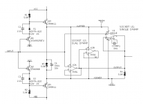
Some people are using the circuit attached below, as the input buffer of their First Watt M2x power amp.
It's a unity gain opamp, whose power supply rails "VUPPER" and "VLOWER" are bootstrapped to the input signal. Thanks to the unity gain connection, this is also the output signal.
Now the music signal is superimposed upon the supply rails. PSRR shoots through the roof, and "common mode distortion" is drastically reduced.
Also of note, the output loading resistor "R4" is bootstrapped so it becomes a constant current source. This helps to linearize the opamp's output stage and reduces crossover distortion.
If you want to see more, google search for "M2x" and "IPS7" on site diyaudio.com
{the funny business with three triangles on the schematic is simple: there are two DIP-8 sockets on the PCB. One of them for dual opamps like NE5532. Another of them for single opamps like LT1122. Builders can try whatever opamp they happen to prefer, whether it be a single OR a dual. But of course only one DIP-8 at a time!!}
_
Attachments
thanks Mark. question is , with OPAMPS like OPA1642 which are unity gain stable and very good common mode rejection , is it really necessary to use such design? I'm trying to keep it simple as possible , while allowing some flexibility to play with different ICs.
See Distortion and Source Impedance in JFET Input Op Amps
You can get some measured improvements with bootstrapping. But in my experience, distortion is already so low it doesn't translate into audible improvements. Same with class A biasing.
This said, I would add a low pass filter at the input of your schematic to keep HF out. Your 1K input resistor is very low too. If your source can drive that, you don't need a buffer at all. I'd use at least 10k. Finally, an output resistor around 47r would be good practice.
Where will you place your volume control ?
A bootstrapped input with BJT somewhat defeats the purpose of a JFET input amp.
I would consider the square wave performance for voltage follower duties. Distortion shouldn't be the only parameter guiding a choice. Opamps can have too much gain for some applications. Compare OPA1641 with ADA4001.
I would consider the square wave performance for voltage follower duties. Distortion shouldn't be the only parameter guiding a choice. Opamps can have too much gain for some applications. Compare OPA1641 with ADA4001.
See Distortion and Source Impedance in JFET Input Op Amps
You can get some measured improvements with bootstrapping. But in my experience, distortion is already so low it doesn't translate into audible improvements. Same with class A biasing.
This said, I would add a low pass filter at the input of your schematic to keep HF out. Your 1K input resistor is very low too. If your source can drive that, you don't need a buffer at all. I'd use at least 10k. Finally, an output resistor around 47r would be good practice.
Where will you place your volume control ?
It's going to be a buffer unit for a multi channel amp. Im not planning any volume control in this unit. the resistor used was intended to participate in RC network for allowing 1HZ and above. should I also put HF filtering and where?
A bootstrapped input with BJT somewhat defeats the purpose of a JFET input amp.
Perhaps so -- the original application didn't care one way or the other. For applications which do care, the BJT emitter followers at the input can be replaced with JFET source followers, and the rest remains unchanged.
For reference here is my buffer article
http://hifisonix.com/wordpress/wp-content/uploads/2015/01/UBx.pdf
I have Gerbers for an SMD version using a Alps RK68 pot a d an LSK389B. I have not built it, but am quite willing to put it up if people are interested.
http://hifisonix.com/wordpress/wp-content/uploads/2015/01/UBx.pdf
I have Gerbers for an SMD version using a Alps RK68 pot a d an LSK389B. I have not built it, but am quite willing to put it up if people are interested.
Last edited:
There is no reason I can think of why this rc network should have such low values though ? Up at least the resistor to 10k and reduce the cap value to 10uF. Or even up to 100k/1uF as the SX has an input impedance around 10k and it doesn't make much sense to have a buffer which is harder to drive than the amp itself, especially with no pot involved.the resistor used was intended to participate in RC network for allowing 1HZ and above. should I also put HF filtering and where?
HF filtering can go right at the positive input of the opamp.
For reference here is my buffer article
http://hifisonix.com/wordpress/wp-content/uploads/2015/01/UBx.pdf
I have Gerbers for an SMD version using a Alps RK68 pot a d an LSK389B. I have not built it, but am quite willing to put it up if people are interested.
I have actually looked at your universal buffer and had plans to incorporate it or at least test it. I found B1 currently much easier to source , parts wise , and since I wanted to have 1 JFET and 1 OPAMP based circuit to compare with , I figured I would start with B1 first and then if I'll like it , I would opt for your build as another comparison.
I did make my B1 close with trim pot bypass option , using TH resistors as I won't need to make any adjustments once I settle for the input resistance.
There is no reason I can think of why this rc network should have such low values though ? Up at least the resistor to 10k and reduce the cap value to 10uF. Or even up to 100k/1uF as the SX has an input impedance around 10k and it doesn't make much sense to have a buffer which is harder to drive than the amp itself, especially with no pot involved.
HF filtering can go right at the positive input of the opamp.
yes of-course , although I think there are issues with distortions in high impedance resistors. probably settle for a 50k or less and a coupling cap for the eq shelve.
so HF right after this LF ?
Some folks wanted to add a volume control on the input and the input bias resistor is quite low at 10 k IIRC.
A general purpose buffer is quite a useful thing in audio.
A general purpose buffer is quite a useful thing in audio.
You screw the pot log taper function up especially if you are using higher value pots like 20 or 50 k ( common values). If you are feeding from a tube source, also problematic.
- Home
- Source & Line
- Analog Line Level
- JFET opamp for buffer