There is nothing special with these caps. The ESR is alright, but i have already had one short out needing replacement. What was good with them is that i had a box of them and they fit my case.
Talking to one of my friends who repairs audio equipment he tells me that as soon as he sees them, he rips them out and replaces them with new caps because if they havent failed yet, they are about too. These are usiually found in power supplies and probably have a -10%/+50% tolerance. I had to meassure a few to find a matching pair.
Talking to one of my friends who repairs audio equipment he tells me that as soon as he sees them, he rips them out and replaces them with new caps because if they havent failed yet, they are about too. These are usiually found in power supplies and probably have a -10%/+50% tolerance. I had to meassure a few to find a matching pair.
Those ROE caps look cool, but aren't anything special. Fine for power supply use though.

I found them in vintage Bang and Olufsen gear, so it has to be something good, but maybe this was "good" in the 70's, not now anymore...I will keep them in case of need to repair old west German radios...many Grundig, Nordmende, TFK and so have them inside...
I'm anxious to receive also some PCB's for this amp....can someone compare this amp with the 3 transistor amp, with BD139 final, also in a long discussion here...just a verdict of which is better or musically, even subjective, best loved?
I'm anxious to receive also some PCB's for this amp....can someone compare this amp with the 3 transistor amp, with BD139 final, also in a long discussion here...just a verdict of which is better or musically, even subjective, best loved?
What about J112? Did someone try them in combination with IRF510? Or can yout tell the difference - other than gate current from datasheet - in this schematic? What should I change in a set of values calculated for J113?found a bag of BF245A JFETs, they seem quite similar to the 2N5484 so im going to see if i can get this working on a breadboard this evening. Just need to find another IRF510 or a pair of similar ones in my collection
Maybe it's a silly question, sorry, but I have very limited experience with j-fet or mos-fet...
Here below is my work of the few last days: all 3 impedance version of this intriguing amp. All are working, nothing measured yet, apart from correct bias, but the listening impressions are awesome, and my greatest surprise is that all versions are fully interchangeable with all kinds of headphones - range 18-300 ohms - with some gain limitations, of course, but fully playable.

I have some mentions - based on my practical approach:
1. I recomend, if you don't have the best quality capacitor for the output C, use in parallel an 1 uF non-polarized one, in my case soldered on the back of the PCB.
2. In the first built version, the "Medium", I used vintage J113, salvaged from an old mixing console and the schematic values were the given ones, with the 330R I got above 2V on the test point. I mounted 390R and the voltage on R4 raised to 2.7V. But in the other two amps I used new On-Semi j-fets (or just hope to be OnSemi, as the store says...) and in this case the correct bias worked only with severely adjusted values, for "Low" I used 120 and 135 ohms - some channel imbalance which I cannot explain, on my tester both fet and mos-fet pairs were almost equal. This was my second amp, the last build was the "High". Here I used 240R and the voltage in the test point is around 4.6V. I strongly recommend, before mounting the R2, to use an adjustable trimmer of 1k, previously measured and adjusted to the schematic value and to choose the right value for you, measuring the voltage in the test point. After that you can replace the trimmer with the closest resistor available, or to use a combination of two if you want to have the absolut exact values as measured.
The power supply I used in all 3 cases is a Nazar power supply, the positive half. It provides very good and clean output, no hum was present at the output, at least in the limits of my hearing and headphones available.
The author of the pcb's I used is here, in this discussion, if he wants, I kindly invite him to show here and if someone wants the files of the projects, feel free to contact him.
By now I just listened to all three amps, in the weekend I try to make some time to put an osciloscope and a generator, but musically these amps earned a good place in my collection, that's sure!
Here is a closer view to the "Medium" version:

The mos-fet's I used in all 3 versions are NOS ones, made 25 years ago by International Rectifier...all measured very close relatively on my multi-tester.

I have some mentions - based on my practical approach:
1. I recomend, if you don't have the best quality capacitor for the output C, use in parallel an 1 uF non-polarized one, in my case soldered on the back of the PCB.
2. In the first built version, the "Medium", I used vintage J113, salvaged from an old mixing console and the schematic values were the given ones, with the 330R I got above 2V on the test point. I mounted 390R and the voltage on R4 raised to 2.7V. But in the other two amps I used new On-Semi j-fets (or just hope to be OnSemi, as the store says...) and in this case the correct bias worked only with severely adjusted values, for "Low" I used 120 and 135 ohms - some channel imbalance which I cannot explain, on my tester both fet and mos-fet pairs were almost equal. This was my second amp, the last build was the "High". Here I used 240R and the voltage in the test point is around 4.6V. I strongly recommend, before mounting the R2, to use an adjustable trimmer of 1k, previously measured and adjusted to the schematic value and to choose the right value for you, measuring the voltage in the test point. After that you can replace the trimmer with the closest resistor available, or to use a combination of two if you want to have the absolut exact values as measured.
The power supply I used in all 3 cases is a Nazar power supply, the positive half. It provides very good and clean output, no hum was present at the output, at least in the limits of my hearing and headphones available.
The author of the pcb's I used is here, in this discussion, if he wants, I kindly invite him to show here and if someone wants the files of the projects, feel free to contact him.
By now I just listened to all three amps, in the weekend I try to make some time to put an osciloscope and a generator, but musically these amps earned a good place in my collection, that's sure!
Here is a closer view to the "Medium" version:
The mos-fet's I used in all 3 versions are NOS ones, made 25 years ago by International Rectifier...all measured very close relatively on my multi-tester.
Very interesting.
I'm actually in the process of putting together this nice head-amp, like you folks.
Confident it will sound great and I generally trust RJM's choices.
Have been also experimenting with PCB design and this is also a great candidate for beginners.
Will probably power it with passive rectification (RCRC). Each capacitor bank will be up to 16000uF (16x1000uF).
If i find a larger enclosure, i might go overboard with separate dual-mono PCBs, dual-PSU and separate transformers.
Gain adjusted for 120Ω cans or lower (down to 32Ω).
Listening to it right now.
Preliminary impressions: A well-defined, full and dynamic sound. Very positive.
It sits on a breadboard at the moment.
The 2 separate PCBs are one for each channel, sharing a common PSU PCB.
Might populate another PSU PCB (with its separate power TX) for a true dual-mono setup.

Schematic:

*actually powering it with 14VDC instead of 12VDC seen above
Preliminary impressions: A well-defined, full and dynamic sound. Very positive.
It sits on a breadboard at the moment.
The 2 separate PCBs are one for each channel, sharing a common PSU PCB.
Might populate another PSU PCB (with its separate power TX) for a true dual-mono setup.
Schematic:
*actually powering it with 14VDC instead of 12VDC seen above
Hello!
Has anyone of you tried other types of mosfets instead IRF510?
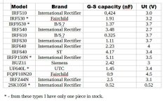
As far as I know, the most important parameters in audio, for a mosfet, are:
Input Capacitance (Ciss) / Output Capacitance (Coss) and Reverse Transfer Capacitance (Crss).
I don't have gear to measure such parameters, but I have a multitester which displays one capacity and one voltage, I think it's the gate-source threshold voltage.
Based on this information, I made this table...After I made 3 version of this amplifier with the originals NOS IRF510, made by International Rectifier, I want to fiddle a bit with this schematic, seeking the best performance. From my measuring, it seems the IRF610 has even less capacity, maybe the G/S capacity. I will try this first, but maybe it could be interesting to test the others, unfortunately I don't have pairs of all the mosfets in the table.
Maybe this curiosity is useless, for such a simple amplifier, still, any documented opinion, based on theory or taken from practical test or audition should be welcome!
The differences in sound I expect to be more significant than the tube rolling, where maybe 10% is true sound difference and 90% placebo...don't shoot, I also like/use tubes! At least the frequency response should be different from one device to another, regarding the capacity differences.
Has anyone of you tried other types of mosfets instead IRF510?
As far as I know, the most important parameters in audio, for a mosfet, are:
Input Capacitance (Ciss) / Output Capacitance (Coss) and Reverse Transfer Capacitance (Crss).
I don't have gear to measure such parameters, but I have a multitester which displays one capacity and one voltage, I think it's the gate-source threshold voltage.
Based on this information, I made this table...After I made 3 version of this amplifier with the originals NOS IRF510, made by International Rectifier, I want to fiddle a bit with this schematic, seeking the best performance. From my measuring, it seems the IRF610 has even less capacity, maybe the G/S capacity. I will try this first, but maybe it could be interesting to test the others, unfortunately I don't have pairs of all the mosfets in the table.
Maybe this curiosity is useless, for such a simple amplifier, still, any documented opinion, based on theory or taken from practical test or audition should be welcome!
The differences in sound I expect to be more significant than the tube rolling, where maybe 10% is true sound difference and 90% placebo...don't shoot, I also like/use tubes! At least the frequency response should be different from one device to another, regarding the capacity differences.
Attachments
One observation: initially I used a 2200uF 25V capacitor at the output. The sound seemed a little flat and dull. I then replaced it with a 2200uF 50V capacitor and the result was that the sound opened up on both ends of the spectrum. It sounds pretty good now.
Any reason why a higher rated cap would make a perceptible difference?
Any reason why a higher rated cap would make a perceptible difference?
For sure it's not the higher voltage rate the reason, but the better capacitor brand. Also you can try to add a non polarised 1uF parallel to the output, the highs may be further better this way. If you have some higher quality 1000uF, this is enough, except maybe for lower than 32 ohms headphones.
The reactance at 20 hz for 1000uF is about 8 ohms, and around 4 at 2200uF. For higher than 32 ohms it's obvious the 1000uF value is enough...
The reactance at 20 hz for 1000uF is about 8 ohms, and around 4 at 2200uF. For higher than 32 ohms it's obvious the 1000uF value is enough...
I think I read somewhere, the higher voltage caps have lower ESR? I don't have the specs for the caps I'm using (both from the same manufacturer: Keltron)
ESR is irrelevant here, maybe better isolation between plates...try also adding 1uF and compare the high frequency response 🙂
Low ESR is recommended.
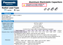
Use Panasonic FC-FR /50V . After a while, a few hours of operation it will sound very good.
I say this from experience.
Do not use standard capacitors.
------------------------------------------
Edit:
Another thing...
Don't parallel MKS capacitors.
It works fine without. If you want to try it anyway, just use MKP.
------------------------------------
Equally important is the power supply.
You can try different options. The sound may be better in some cases.
Last edited:
My best results with this type of amplifier, regarding power supply, is a lead battery, 12V and 5Ah, enough for two days long listening....and a standard lead-acid accu charger....from a scrapped 19V laptop charger and a schematic based on LM317. I used a double switch for standby/charge - battery listening to completely separate the mains circuit from the battery. No hum at all and very clear, detailed sound.
The voltage can be a little higher than 12V, but there's no problem. If you notice suspect heating of the mosfets, test and modify the resistor R2 to obtain the indicated voltage on R4. I experienced many different values because of the spread of J113 characteristics...I recommend using a temporary 1K adjustable resistor and put in the amplifier the measured value....maybe with 2 parallel resistors to fit a non standard value.
The voltage can be a little higher than 12V, but there's no problem. If you notice suspect heating of the mosfets, test and modify the resistor R2 to obtain the indicated voltage on R4. I experienced many different values because of the spread of J113 characteristics...I recommend using a temporary 1K adjustable resistor and put in the amplifier the measured value....maybe with 2 parallel resistors to fit a non standard value.
Last edited:
- Home
- Amplifiers
- Headphone Systems
- JFET-MOSFET headphone amplifier J-Mo 3