It now seems that the only purpose of starting this thread was to promote the product for genereating revenue.
Nothing wrong with that, but it should have been placed in the Commercial Sector.
Don't see it. Pavel's webpage still clearly says 'no sales since 2012'. Given how cluttered threads become starting one to post a specific topology for discussion seems completely logical even if some final details with held. Each person has a right to control their own disclosure even if others don't agree with it.
Hi Bill,
Of course, everybody has the right to not disclose.
But why then show a undocumented circuit diagram in the first place ?
Doesn’t that mean that you want to keep some for yourself ?
The only reason to keep it secret that I can think of is that you either want to sell the design or still want to sell the product yourself.
Not producing any answers relating to inconsistancies, means that the thread was seemingly not intended to start a discussion either.
It’s all a mystery to me, but again, anyone is entitled to do what he or she likes but so is my good right not to believe that there are no hidden commercial intentions behind this all.
Hans
P.s. as a matter of fact, a BOM is the least I’m interested in, I was just pointing at only a few of several inconsistancies in graphs and data.
I have put the generic model into LTspice, using 2SK170 and 2SJ74 for the input and 2SK1056 and 2SJ162 for the output.Sorry but it is the inductive impedance magnitude in parallel with 47k input resistor that makes the noise. Please let's not speculate about iron losses, if you put the circuit into Microcap you get the same noise rise. And Microcap knows nothing about iron losses in the ideal inductor used for the simulation.
A gave the input Fet's 1 mA bias each and the Mosfet's an idle current of 23mA.
With that setup, I was completely surprised by the very low noise level at the input.
With 50R at the input the equivalent A-weighted input noise for this Riaa amp gave 631pV/rtHz, that's adequate for almost all MC Carts !!
A 50R MC Cart would have a S/N of 75dB(A) ref 0.5mV@1Khz.
This of course under the premise that my LTspice models for both input Fets are correct.
But if so, it is the first amp that I came across that could be used for MC and for MM.
A second amp directly behind this amp with switchable gain could adjust for the overall required MM or MC gain, at the same time giving a low impedance output impedance, making the connection to a preamp less susceptible for EMF from outside.
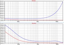
The images below are resp. showing the unweighted input and output noise at 36dB gain for a 50R MC Cart in Red and for a 700mH/1.3K Orto Cart, terminated with 47K//125Pf in Blue.
Hans
Attachments
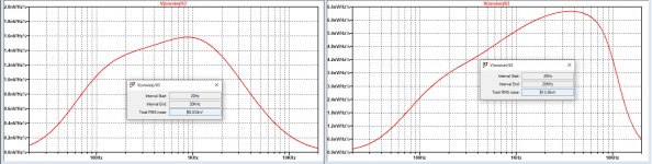
And here for completeness the A-weighted noise spectra for a 50R MC Cart and a 700mH + 1K3 MM Cart terminated with 47K//125pF.
20*log(0.5mv/89nV) = 75.0 dB(A) for a 50R MC Cart ref 0.5mV@1Khz
20*log (5mV/613nV) = 78.2 dB(A) for a Orto 2M Blue Cart ref 5mV@1kHz.
equivalent A-weighted input noise with the MC Cart is 89mV/Sqrt(20Khz)=630pV/rthz
Equivalent A-weighted input noise with the Orto Cart is 613nV/Sqrt(20Khz) =4.4nV/rtHz
For both MC and MM excellent figures.
Hans
Attachments
Those last two equations make no sense, as the noise bandwidth of a RIAA correction filter followed by an A-weighting filter is only 3212 Hz...3220 Hz (relative to the gain at 1 kHz), not 20 kHz.
RIAA and A, 1 Hz ... 1 MHz: 3220.23 Hz
RIAA and A, 20 Hz ... 20 kHz: 3214.16 Hz
IEC-amended RIAA and A, 1 Hz ... 1 MHz: 3218.79 Hz
IEC-amended RIAA and A, 20 Hz ... 20 kHz: 3212.71 Hz
With 700 mH cartridge inductance, the 47 kohm termination resistor's noise is already close to 10 nV/sqrt(Hz) RIAA- and A-weighted average.
Last edited:
Marcel,
Sorry, but I have no idea what are trying to tell.
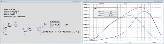
See image below for a 700mH + 1k3 Cart terminated with 125pF//47K,
noiselessly processed by Riaa and A-Weighting, with a gain of 0dB at 1kHz,
output noise is 552nV and you also see the noise contribution from the 47K and the 1k3 resistors, resp V(r2) and V(r1).
I don't understand your 10nV/rtHz for the 47K resistor.
A flat Amp with 3.9nV/rtHz input noise will produce exactly the same input noise over a BW of 20Khz [3.9nV*Sqrt(20Khz) = 552nV].
Maybe this equivalent noise figure is not what you are used to look at, but I find this figure quite informative.
Hans
Sorry, but I have no idea what are trying to tell.
See image below for a 700mH + 1k3 Cart terminated with 125pF//47K,
noiselessly processed by Riaa and A-Weighting, with a gain of 0dB at 1kHz,
output noise is 552nV and you also see the noise contribution from the 47K and the 1k3 resistors, resp V(r2) and V(r1).
I don't understand your 10nV/rtHz for the 47K resistor.
A flat Amp with 3.9nV/rtHz input noise will produce exactly the same input noise over a BW of 20Khz [3.9nV*Sqrt(20Khz) = 552nV].
Maybe this equivalent noise figure is not what you are used to look at, but I find this figure quite informative.
Hans
Attachments
If you check the integrated output noise due to just the 1.3 kohm, you will see it is roughly sqrt(4 k T * 1.3 kohm * 3214.16 Hz * gain at 1 kHz), not sqrt(4 k T * 1.3 kohm * 20 kHz * gain at 1 kHz).
Let’s agree that we look in a different way at the same things.
For me the equivalent input noise is just another figure that I like to use, but you seem to have your own methodology.
But the only thing that really matters is the S/N, there can be no disagreement on that.
Hans
For me the equivalent input noise is just another figure that I like to use, but you seem to have your own methodology.
But the only thing that really matters is the S/N, there can be no disagreement on that.
Hans
I don't think Hans is doing that, he is just creating his own figure of merit. He is comparing the heavily frequency shaped noise of the circuit in a 20k BW to what flat noise in a 20k BW gives the same rms noise, some might find that useful.
Hans, of course you can calculate whatever you want, but when you write "Equivalent A-weighted input noise with the Orto Cart is 613nV/Sqrt(20Khz) =4.4nV/rtHz" I get the impression that you mean that 4.4 nV/sqrt(Hz) of white voltage noise at the RIAA amplifier input would produce the same integrated A-weighted noise at its output as the noise that is actually there.
Apparently you don't mean that at all, you mean that 4.4 nV/sqrt(Hz) of white voltage noise at the input of some fictitious amplifier with a 20 kHz bandwidth that has the same gain as the RIAA amplifier has at 1 kHz, produces the same amount of noise at the fictitious amplifier's output as there is at the output of the A-weighting filter that the RIAA amplifier is connected to. That's such an unusual definition of equivalent input noise that I would never have guessed that that is what you mean.
So for example, the equivalent A-weighted input voltage noise of an NE5534A would be 3.5 nV/sqrt(Hz) * sqrt(3214.16 Hz/20 kHz) ~= 1.403 nV/sqrt(Hz) according to your definition.
Marcel,
Glad we are finally lined up after my formulation causing some confusion.
That’s why in posting #107 I tried to make things completely clear with an example and now with Scott’s additional support we are all set now.
Hans
Glad we are finally lined up after my formulation causing some confusion.
That’s why in posting #107 I tried to make things completely clear with an example and now with Scott’s additional support we are all set now.
Hans
Conversely, the almost 10 nV/sqrt(Hz) from my post 106 means that the termination resistor adds almost as much noise to the integrated RIAA- and A-weighted noise as a 10 nV/sqrt(Hz) noise voltage source at the input of the RIAA amplifier would. This corresponds to about 4 nV/sqrt(Hz) at the input of your fictitious 20 kHz-wide amplifier, showing that your 4.4 nV/sqrt(Hz) comes almost entirely from the termination resistor.
Then a LF356 would be perfectly ok as a fet preamp for riaa, including the fact that it has a max supply rails of +-22v and the H can can deal with the heat too...It happens that i have about 30 LF 356H military cans and i though of giving them some purpose.Although Jung stated that its distortions are awfull i never listened to him in some other op-amps cases as OP275 which measures like hell and sounds fine...
With 10 nV/sqrt(Hz) from the termination resistor, 12 nV/sqrt(Hz) from an LF356, 4.6 nV/sqrt(Hz) from the cartridge's wire resistance, neglecting other contributions and with 3214.16 Hz noise bandwidth, the total noise without record surface noise would be 923.18 nV RIAA- and A-weighted. The Orto 2M Blue produces 5.5 mV at 5 cm/s, so the noise level would be equivalent to -75.5 dB(A) relative to 5 cm/s, 1 kHz. I expect that in reality you will get some 1 dB to 1.5 dB more noise due to cartridge iron losses, but that's just an educated guess.
If that's good enough for you, then an LF356 will do. Record surface noise is typically -60 dB(A) with respect to 5 cm/s, 1 kHz, according to xx3stksm's measurements of a new record played dry.
If that's good enough for you, then an LF356 will do. Record surface noise is typically -60 dB(A) with respect to 5 cm/s, 1 kHz, according to xx3stksm's measurements of a new record played dry.
I think i lost some good time with tape heads lowest noise preamps in cassete decks until i realized that it's only the dolby system that can save the day as the tape hiss was impossible to fight in a different manner.And the Dolby system reduced also the preamp noise too ...My main concern related to amplifying a signal that's 0.1...2 db distorted right from the cartridge output would still be the highest input signal it can take to fight ticks and pops as most people are lazy and don't clean a record every time they listen to it, myself included.For this purpose, an op-amp able to take +_22v max supply is way better than a modern one that can only go to max +-18v and i listen to a good bunch of +_18 supplied phono preamps that sound like sh...t on dusty records at 33RPM. At 45 RPM most of them will sound good though.There are lower supply rails preamps that sound well, but they are using either passive equalization or starved input bias with BJT input...Not talking again about Scott's full fet version that can fight clipping as i don't have so many fets to use on his design...Some say that current feedback can be as effective as passive networks at dissipating the ticks and pop's energy , it might be that too, although i can't claim that i can prove that with math calculus...
Compare the max o/p of a lf356 vs a newer rail to rail type such as opa1656 at their max supply V
@rsavas I hate the fact that most new op-amps that are advertized as good for phono are smd ones...have you touched one while working?They are damn hot while working at 1...2ma of idle current...I don't trust them enough for that reason.With old op-amps i can use a buffer and their output parameters become good enough for anything i need.At least OPA1652 has a thermal pad...
Yes I have touched them while in operation. I trust that TI knows what they are doing. The pcb layout is important to put a ground plane under the devices, with or without the package thermal pad, this will allow the heat to be dissipated. Power is also dissipated through the leads. I have been using smt for now 40 years now = old hat. If lf356 is your choice, that is your option, probably still in production for people like you and legacy designs 🙂
My point was about max o/p of a lf356 vs newer rail to rail devices, but you have avoided my response and focus on another design issue.
My point was about max o/p of a lf356 vs newer rail to rail devices, but you have avoided my response and focus on another design issue.
Ok then..what the hell means "max o/p" ? This is not a term you find in any datasheet so i just assumed it's about output power. Google can't find this term either related to operational amplifiers and i don't find myself smarter than Google. Are you one of those guys using fancy terms just to look like the ultimate guru? Tell it straight, as an engineer if you think you're one of them!
Last edited:
- Home
- Source & Line
- Analogue Source
- JFET input phono preamp for MM