Kean,
I have posted numerous square waves in this thread, including a comprehensive PDF with a wide variety of loads and scope shots. However I will do it one more time 🙂 what load would you like?
As I have mentioned the square wave performance of my circuit is pretty poor - lots of ringing, but I like the sound this way.
If you want me to do the other test I need a little more info on how to do it (in very basic english) 🙂
It turns out my calibrator really is inadequate for this purpose. I must fix my signal generator... Really I don't think these tests will show us anything important, so I don't think it matters.
To make the load test, you should measure the output impedance of your signal generator. A DMM will probably do, and if your generator is a good one, it will probably have 50R output impedance. Set a predefined test current, say 30mA. 50R*30mA=1.5V; set this as your generator output voltage as seen on the scope without anything else connected. Then, connect generator ground to amp ground, and generator output to amplifier output, and examine amplifier's output voltage on the scope. This is a good time to look at the max output current on your generator's datasheet, so you don't accidentally hurt it.
- keantoken
Have you guys seen Luigi's measurements of transient response http://www.diyaudio.com/forums/anal...h-preamplifier-part-ii-1470.html#post2667065? Seems a very worthwhile test & would be an interesting verification of both the test's efficacy & the two different amp's transient response & sound.
He seems to concur with SW's observation that his amp sounds wonderful even though the measured square wave response is poor!
He seems to concur with SW's observation that his amp sounds wonderful even though the measured square wave response is poor!
Kean,
My sig gen is pretty decent and has two outputs - 60R and 600R, so no problems there.
Sorry to ask the obvious question, but I take it this test is done with the amplifier on?
Interesting reading, jkeny!
My sig gen is pretty decent and has two outputs - 60R and 600R, so no problems there.
Sorry to ask the obvious question, but I take it this test is done with the amplifier on?
Interesting reading, jkeny!
Kean,
........
Interesting reading, jkeny!
Yep, I asked the mods to break it out into it's own thread as I think it needs more exposure/investigation!
You're correct SWF. 600R will be better. A swept sine test in this configuration would be gratuitous. Just make sure you can increase the current enough to get over the noise without burning out the generator's series resistor. Even if the flat part of the square wave can't be seen, usually the scope can trigger on the spikes produced at switching, which may only be visible on fast timebase (horizontal sweep) settings.
I read through that and still wasn't sure what kind of test they are talking about. But, based on that discussion, and an obscure hint by one prominent member, I suspect that a saw or triangle wave generator, used in conjunction with differential scope mode, is a very relevant test. After this corroboration I will have to experiment. 😉
- keantoken
Hi Hugh,
I might miss Graham's original point, but I would think he is saying that this specific error signal, coming from op shift of the JFET, cannot be corrected by even the best feedback loop as it can only compare the output to the "copied" input signal at the source, shifted down by the actual Vgs.
So we must strive to keep Vgs as constant as possible,
- Klaus
100%
This is easily done by using a Jfet as the GS resistor of the VAS. I suspect SWF has already tested this and found it didn't sound better to him. It may decrease open-loop bandwidth and make it harder to pleasingly compensate the amp, but that is just my theory.
I like the approach of decreasing open-loop distortion so that less feedback can be used. This generally creates a faster, more reliable, and sometimes simpler amp. This also puts less demand on the input stage to fix the errors of everything else.
SWF, I keep forgetting to mention this, the load test should be done without any load connected, including the Zobel.
- keantoken
Well, I equalized my speakers using a random dynamic microphone sitting around, and this is what I got.
Guess I will have to find some thick rugs and staple them to the back of my OB to damp the LF stuff...
I found an electret sitting around, and taped a pen barrel onto the end, though I think it has some resonance issues.
- keantoken
Guess I will have to find some thick rugs and staple them to the back of my OB to damp the LF stuff...
I found an electret sitting around, and taped a pen barrel onto the end, though I think it has some resonance issues.
- keantoken
Attachments
Last edited:
Kean,
Interesting work.
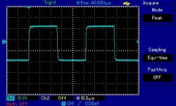
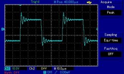
Here are the 20kHz square waves into 7R and 7R + 100nF. No compensation whatsoever.
As I said, terrible. But sounds fantastic!
I am running only 7mA in the VAS, hence the slow fall time. Also running output at 1.2A which sounds absolutely surreal.
Will get on to your other test soon.
Interesting work.
Here are the 20kHz square waves into 7R and 7R + 100nF. No compensation whatsoever.
As I said, terrible. But sounds fantastic!
I am running only 7mA in the VAS, hence the slow fall time. Also running output at 1.2A which sounds absolutely surreal.
Will get on to your other test soon.
Attachments
The second mentioned load so as the curvature from second image indicates a not present serial network consists of two devices in parallel:Kean,
Interesting work.
Here are the 20kHz square waves into 7R and 7R + 100nF. No compensation whatsoever.
As I said, terrible. But sounds fantastic!
I am running only 7mA in the VAS, hence the slow fall time. Also running output at 1.2A which sounds absolutely surreal.
Will get on to your other test soon.
An inductor (air coil of approximately 10-20 windings) and a resistor.
This coil I missed also by various commercial amps, e. g. Naim Audio's NAP110, NAP160 and NAP250 (thus it is to understand, why their cable to the loudspeakers have this special look.
Speaker Cables Naim NAC A5 SPEAKER CABLE | hifix.co.uk.
Should this really be the best solution respective the royal way ??
I would say, no. The use of such a coil for prevent "ring-ring" by square-wave signal and capacitive loads is the right solution - so I think.
Any real inductor will resonate with a capacitor. You cannot prevent ringing. Actually SWF's plot looks benign to me. I suspect a series inductor may in fact increase ringing.
- keantoken
- keantoken
Should this really be the best solution respective the royal way ??
I would say, no. The use of such a coil for prevent "ring-ring" by square-wave signal and capacitive loads is the right solution - so I think.
Greg,
never mind that it sounds fantastic - will you pull yourself together, grit your teeth and just follow the rules ! your wayward attitude here is well out of order and must change.
This is not about enjoyment this is about RULES !!!
😉
Ha, thanks mike.
Actually, I have tried an output inductor and it did not seem to help much. One thing I am doing is running "naim style" cables - two separate wires not joined together. It slightly improves the ringing and is a fairly benign way to add a little inductance and keep the capacitance low. I quite like my tailored solution with my specialized audio cables made of $1/5m hookup wire that sounds brilliant. I can see the marketing ploy now.
I look forward to you guys posting some square waves too. I found that the ZVP2110G and hybrid MOSFET ccs seemed far better in this regard, but this is the circuit I like the sound of most.
As I have said, with my particular circuit choice it takes ridiculous amounts of compensation to get rid of this ringing, all of which sound worse to my ears than just leaving it there.
A little more complicated....
For some reason I feel the need to go more complicated and I remember mike had some good simulations by using a cascoded BJT vas.
This is where I'm heading... might be better in a new thread but I thought I would see what you guys here think first.
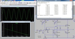
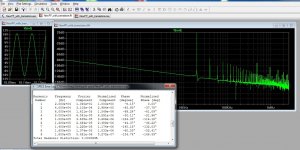
The cascoded VAS has very low distortion, but boy does the spectrum get messy at 20kHz. Looks good at 1kHz though, huh? Note the simulation is at 20v P-P!
For some reason I feel the need to go more complicated and I remember mike had some good simulations by using a cascoded BJT vas.
This is where I'm heading... might be better in a new thread but I thought I would see what you guys here think first.
The cascoded VAS has very low distortion, but boy does the spectrum get messy at 20kHz. Looks good at 1kHz though, huh? Note the simulation is at 20v P-P!
Attachments
Actually I thought that the cascoded BJT VAS would work well with the Jfet i/p - adding more linearity, gain and extra speed compared with a single BJT VAS that sounded undynamic and lifeless.
Even if distortion is super-low, the 98% criteria is probably still satisfied. I think the compensation scheme may matter just as much as for the Jfet versions though.
- keantoken
- keantoken
Standard output inductors are damped with parallel 5-12 ohms and do kill ringing with capacitive loads. That is the principal reason they are fitted.Any real inductor will resonate with a capacitor..... You cannot prevent ringing.....
- Status
- Not open for further replies.
- Home
- Amplifiers
- Solid State
- JFET input, MOSFET VAS, LATERAL output = Perfect!!