My thoughts are that spikes that pass through all stages unclipped, have less audible effect on the final sound than spikes that at some stage get clipped.
This clipping can be at any stage in the reproduction chain. RIAA pre-amp, ClassA gain stage in a Pre-amp, buffer on the output of any stage. Power amp input stage or VAS stage.
We all already know that clipping in the final output stage is not as nice as passing unclipped.
This clipping can be at any stage in the reproduction chain. RIAA pre-amp, ClassA gain stage in a Pre-amp, buffer on the output of any stage. Power amp input stage or VAS stage.
We all already know that clipping in the final output stage is not as nice as passing unclipped.
This is a paper that I saw just posted over on the objectivist Vs Subjectivist debate thread & might have some relevance to your discussions here. BTW, well done all here, I've cited this many times as a shining example of just what progress can be made when the two camps agree to respect one another "Perception & Thresholds of Nonlinear Distortion using Complex Signals"
Ohhh....my old engineering school... Always knew they were good at something...🙂
Bet you wish you were there now 🙂
Hmm, onto the second page now? That's no good......
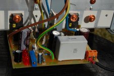
Here's the latest board design, a bit more refinement, moving ahead.
Greg is now in Greece, and vows on return home to build furiously. All the ZVP2110G and DN2530 semis are ordered and should be in the mailbox when he's back!
I'm very enthusiastic about this amplifier.
Cheers,
Hugh
Here's the latest board design, a bit more refinement, moving ahead.
Greg is now in Greece, and vows on return home to build furiously. All the ZVP2110G and DN2530 semis are ordered and should be in the mailbox when he's back!
I'm very enthusiastic about this amplifier.
Cheers,
Hugh
Attachments
Hmm, onto the second page now? That's no good......
Here's the latest board design, a bit more refinement, moving ahead.
Greg is now in Greece, and vows on return home to build furiously. All the ZVP2110G and DN2530 semis are ordered and should be in the mailbox when he's back!
I'm very enthusiastic about this amplifier.
Cheers,
Hugh
Looks tidy Hugh.
But i do not understand why you but in the cutline. Are you not afread that the copper will delaminate from the board (fr4).
Even with breakline using holes in the breakline. The boards has a tendency to delaminate.
IMO it would be better to add more blade terminals and then people could remove the psu caps and rectifiers.
But it is maybe a little late i am saying this.
- Sonny
Yet another Fetzilla PCB
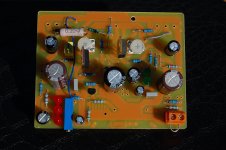
I have made a new PCB for the Fetzilla using Swordfishy IRF9610+610 schematics. This IRF9610 CCS (LED+IRF610) version sounds much better than BJT bootstrap version that I build earlier.
The vocal range is as sweet as before, bass is much better, it just lack a bit of silky highs; otherwise the sound is perfect.
I used toner transfer to make the PCB.
Attachments
Would I be accurate in observing that amplifiers which use a output snubber (C9+R17) to aid in stability also tend to sound better?
- keantoken
- keantoken
IRF9610 and IRF610 is the version I recommend.
Glad to hear it can give pleasure when listening.
Glad to hear it can give pleasure when listening.
Fetzilla PCB (Swordfishy-IRF) version
Attached are PCB files.
PCB is single-sided (106 x 76 mm). It need two ground connections to the star ground - G1 for signal ground, G2 for the Output FET & Zobel.
C1 can be any film cap with lead spacing from 15 to 27.5mm
For R6 & R8, you can use almost any trimpot or fixed value resistor in your parts-bin.
For P1(5K VR), use multi-turns trimpot like 3296Y or 3296W.
For U4 (VAS), either IRF9610 or ZVP3310A or ZVP2110A can be used.
For U1 (CCS), either IRF610 or DN2530 can be used.
Happy building.
Cheers, Stanley
Attachments


Would I be accurate in observing that amplifiers which use a output snubber (C9+R17) to aid in stability also tend to sound better?
I think it depends on the amp and the preferences of the listener.
Peter Daniels has said he prefers the sound of his chip amps without o/p snubbers even though the chip manufacturer recommends them.
JHL said that stabilising measures improve the sound.
Some like fast & exciting others smooth & mellow.
IRF9610 and IRF610 is the version I recommend.
Glad to hear it can give pleasure when listening.
Hi lineup,
The IRF9610 & IRF610 version sounds very good. A big thankyou to you for starting this thread; Many thanks to Greg & others who proposed & build many different versions.
Cheers, Stanley
Lineup,
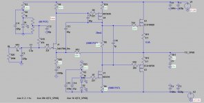
Here's my attempt at a schematic.
Performance is not wonderful because loop gain is not high,
Hugh
G'day Hugh 🙂
Perhaps somewhat off topic but regarding the NFB in your schematic I have often thought that if the signal at the FET source is not =exactly= the same as the signal at the gate then the feedback signal is subtracting from an erroneous version of the input signal and therefore the resulting signal is not properly error-corrected. I imagine the perfect feedback arrangement is a virtual earth summing junction as used in an inverting opamp circuit. What do you think?
Last edited:
Circlotron,
Just for clarity of understanding, would you still think that it is not exactly the same at source & gate if the device has both constant current through it, and voltage across it ?
Just for clarity of understanding, would you still think that it is not exactly the same at source & gate if the device has both constant current through it, and voltage across it ?
Stan,
Well done.
Great that you have confirmed my suggestion that the sound is better with mosfets in the VAS and a CCS, especially the bass. Turns out my ears aren't so bad after all 🙂
Now, to restore the sweet treble you are missing, remove the agricultural 9610 and swap it for a zvp3310a. This will give you good highs, mids and treble.
Thanks for building and posting.
Greg.
- Status
- Not open for further replies.
- Home
- Amplifiers
- Solid State
- JFET input, MOSFET VAS, LATERAL output = Perfect!!