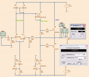
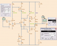
This is the most perfect amplifier I have spiced.
It is simple but yet very, very good.
- JFET input with minimal offset problems.
- MOSFET VAS for speed and gain
- LATERAL output for be a light load to VAS
When CLass AB operation, 350mA bias, it shows only
THD 0.00018% at 1 Watt
And there is almost no increase of THD at 25 Watt output
Enjoy!! 🙂
---------------------------
EDIT:
For more building the final stuff and details, look for FETZILLA
in this AKSA forum: AKSA - diyAudio
Attachments
Last edited:
Umm, but, could you explain that three statement? I remember that your previous thread looking for beautiful small distortion.
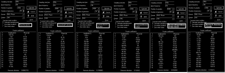
This is sim results distortion figure of some best output stages. Test condition is 10kHz +/-20V output and additional 10kHz, 0.5A current source connected at its output.
Single ended mosfet has higher distortion, but it has higher drop voltage compared to non classA mosfet and SE sounded better than classA. If you like distortion, you shouldn't follow many people that makes their amp suitable to drive resistors, but make your amp best to drive real loudspeaker.
Attachments
The simulation looks promising indeed. Do you have plans to build it ?
Or does your simulation program allow to use models with some tolerances
to resemble "real world" conditions ?
I wonder how sensible this circuit will be to parameter variations, if it´s not
(with reasonable matched parts) it´s certainly worth a try.
Or does your simulation program allow to use models with some tolerances
to resemble "real world" conditions ?
I wonder how sensible this circuit will be to parameter variations, if it´s not
(with reasonable matched parts) it´s certainly worth a try.
Single ended mosfet has higher distortion, but it has higher drop voltage compared to non classA mosfet and SE sounded better than classA.
Edit: Single ended mosfet has higher distortion, but it has higher drop voltage and SE sounded better than normal classA with same bias (5A),
Member
Joined 2009
Paid Member
I think it looks very good. I heard though, that Laterals are more obsolete than most vacuum tubes ?
Lineup, I think Spice is lying sweetly to you... this is not a new configuration, and doesn't seem to change anything...
_-_-bear
_-_-bear
I think a cascode would be good...So you have a little more driving force on the mosfet capacitance...will the input fets not overheat with that Voltage and current....On the limit I think..normally I like to have app 10-12 v over the fet's and then let them run close idss...
Could also be made like the balanced French concept you were toying with in the other thread...🙂
Could also be made like the balanced French concept you were toying with in the other thread...🙂
Cool... I have been following your new circuit Lineup. This could be the "mosfet-based AKSA" I'm looking for. But I don't think I can find the ZVP mosfets. The IRF610, nah... they are horrible. How about the available lateral 2SK214 for the VAS?. Otherwise, 2 stages of bipolar is preferable imo.
And I don't understand why BD139 for the input current source?
Ups, I forget that I have been looking for the simplest topology without constant current sources...
And I don't understand why BD139 for the input current source?
Ups, I forget that I have been looking for the simplest topology without constant current sources...
Last edited:
this is not a new configuration, and doesn't seem to change anything...
_-_-bear
The JLH? It is all designers' reference.
10mA and 50V 😉And I don't understand why BD139 for the input current source?
That's the reason why I have doubt. It is quite high for the difference amplifier. Thermal drift and noise could be a problem.
If you make a LED based current source the thermal balance will be better...
I don't believe that it has something to do with thermal tracking (linearity), but LED based current source has been long known for its good sound.
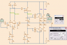
Here a new take on JFET input, MOSFET vas and MOSFET output.
It does 48 Watt RMS before clipping in Class AB (bias is 200mA).
The only bipolar are the drivers: 2SC2911/2SA1209
I use them drivers to get 12 mA onto gates of IRFP240.
Power supply are trafos 2x24 VAC, 200VA for +/-35 Volt rails.
One trafo for each channel.
To setup you need to seek a resistance R8 that give ~5 mA through your JFET 2SK170BL at 35 Volt
Then chose feedback resistor R9 for gain like x20
After this you can adjust R1 (632 Ohm) for zero at output.
Then adjust R4 (4.95 kOhm) for 200 mA in the output devices.
Performance.
THD at 1 kHz is low.
0.0008% at 1 Watt
0.0060% at 42 Watt
The good thing is that 2nd harmonic is very dominant at all levels.
The sound is probably very MOSFETish! 🙂
Enjoy 🙂
Attachments
The 2SK/2SJ pair certainly are rare now, but maybe these could work as an alternative:
Mosfets/Modules - Lateral MOSFETs - Class D
or
ECX08N16-Z
ECX08P16-Z
These seem to be readily available laterals. Your first circuit modelled as very nice performance.
Mosfets/Modules - Lateral MOSFETs - Class D
or
ECX08N16-Z
ECX08P16-Z
These seem to be readily available laterals. Your first circuit modelled as very nice performance.
Diving the Jfet right at the limit...a 10-12V cascode would be good....🙂
What is the reason for the bipolar driver stage....can't you just pull enough current through the mosfets to drive the laterals directly..??
M
ohh sorry didn't see you changed to IRF's....
What is the reason for the bipolar driver stage....can't you just pull enough current through the mosfets to drive the laterals directly..??
M
ohh sorry didn't see you changed to IRF's....
Last edited:
The good thing is that 2nd harmonic is very dominant at all levels.
The sound is probably very MOSFETish! 🙂
Enjoy 🙂
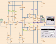
Umm., could you explain that MOSFETish? What kind is it?
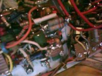
This one using cheapo MOSFETs, but this prototype is best sounded that I have, and best sounded among all amplifiers I ever tried and heard. I listen it almost all few day long (still play when I sleep) without listening fatigue. Best sound reached when driving headphones directly (most beautiful high frequency), but my motorola earpiece burned by this amp when crack input from bad connector happen. Finished in last few days.
Attachments

![test.wmv_snapshot_00.00_[2011.04.24_16.34.28].JPG](/community/data/attachments/204/204071-ef607eb3338fa397462a4c4cf1696d12.jpg?hash=72B-szOPo5)
- Status
- Not open for further replies.
- Home
- Amplifiers
- Solid State
- JFET input, MOSFET VAS, LATERAL output = Perfect!!