What is the voltage at the Drain of the JFET. It needs to be at about the middle of your supply or a little bit lower. Sounds like maybe the current is off a bit (Maybe high?). You can play with the Rs a little or the Rdrain or the supply and see if you can get some improvement. You want to get the JFET drain at about 8-9V.
Sound just like the problem I had. Power supply was not right. Check your power supplies. If you have an 18v cordless drill or other 18v electric hand tool, use it for the PS. Do you get the same thing? Be sure you have several volts DC higher before the rectifiers.
Thanks guys...
in answer to 6L6, sine wave is clean to 1.5v or so...at higher voltages... bottom of sine starts to clip.
I'll try the suggestions so kindly made...
in answer to 6L6, sine wave is clean to 1.5v or so...at higher voltages... bottom of sine starts to clip.
I'll try the suggestions so kindly made...
Here's the problem...I put in 1 volt at 1kh and get out nearly 8 volts. But when I look at the output on an oscilloscope, the bottom going swing is clipping badly. In fact, the bottom going swing starts clipping when output is measured at 1.6v.
What to do???
Thanx
By the way, I used the jfet boz boards from Jim's Audio on Ebay. They are pretty neat, and include a power supply circuit.
Hi,
The right supply voltage varies depending the jfet's idss (For get a low distortion)
IMMO for get more output voltage, you must choose the V jfets instead BL, and raise up the supply voltage to near of 25V to 30V.
Here you have a mod for get a voltage fine tuning for this board
Regards
Last edited:
I notice that when I put 30 volts on the rail...I can get 5.6 volts out of the pre amp without clipping...beyond 5.6v I get the onset of clipping...
I thought 18 volts was the sweet spot...should I operate this preamp at 30volts??? or stay at 18 volts and adjust the drain resistor...I haven't tried working with the drain resistor yet...
I thought 18 volts was the sweet spot...should I operate this preamp at 30volts??? or stay at 18 volts and adjust the drain resistor...I haven't tried working with the drain resistor yet...
Hi,
The sweet spot depends of the jfet idss, the BL is on the 6 to 12 range, and the V is on 10 to 20 range, more Idss = More supply voltage voltage.
Take a look this message on this thread.
For a sweet spot fine tuning your need a distortion analyzer (Or a PC with a sound card and FFT program) and a variable power supply (such as my post before).
Regards
There is no reason to be focusing on the "sweet spot" until you understand why you have a non symetrical output waveform. I think the first place to look is the drain of JFET. The Idss value of the device you have is likely the most important variable in the problem. But, I suppose you have what you have? And, the suggestions to mess with it are not going to come with a new JFET, with those designers personal favorite Idss values. Generally those comments are correct. A higher Idss value device ussually gives the best results when set up correctly. But, is that what N.P. uses in the production units?
As I said, knowing the drain voltage you have now, will give you insight into what to change and how much to change it, to get close to a "sweet spot" without a new JFET.
Just my 2cents. And just trying to help.
As I said, knowing the drain voltage you have now, will give you insight into what to change and how much to change it, to get close to a "sweet spot" without a new JFET.
Just my 2cents. And just trying to help.
Sounds to me like your current is high. This means your JFET Drain is to low of a voltage. You could lower your Drain R or increase your Rs. I would play with the Drain R.
Increasing the supply is also an option. But, with that comes power dissapation? Is the current to high??? You could measure the actual R of the Drain R, and measure the in circuit voltage and you will know the current in the circuit.
Increasing the supply is also an option. But, with that comes power dissapation? Is the current to high??? You could measure the actual R of the Drain R, and measure the in circuit voltage and you will know the current in the circuit.
thanks for the advice...
with power supply at 18.5 volts and drain resistor set to 1000 ohms, the voltage on the drain of the jfet is 9.4 volts (measured between drain and ground). Onset of clipping is now 3.6volts and is symmetrical. The input signal to the pre amp is .3 volts. These voltages are measured by a meter so they are rms. The current through the drain is 8.6ma.
Does this sound right???
If you have a clean output from the JBOZ, the next question is how much gain do you need? 3.6v will get most 'normal' amps well past full output. You might be done. 🙂
She was a Treeing Walker CoonHound. Similar to the American Foxhound. But, she's gone 🙁 I lost her back in June to an ear infection that spread to her brainstem/spine. I should change my avitar.

A two tips for the jim's board (A copy of Manu board)
-Change R1 to 1,5K Ohm
-The mosfet on the power supply drops 4V, for 16V on R7, you need set the zenners to 20V. But with 9,7mA Idss, I would try with 20V (24V before mosfet)
-Change R1 to 1,5K Ohm
-The mosfet on the power supply drops 4V, for 16V on R7, you need set the zenners to 20V. But with 9,7mA Idss, I would try with 20V (24V before mosfet)
You can not expect that much usable output from this circuit....Onset of clipping is now 3.6volts and is symmetrical. The input signal to the pre amp is .3 volts. These voltages are measured by a meter so they are rms. ...
According to Nelson's measurements (post #58 of this thread) the THD at 2V is 5%
QUOTE
with power supply at 18.5 volts and drain resistor set to 1000 ohms, the voltage on the drain of the jfet is 9.4 volts (measured between drain and ground). Onset of clipping is now 3.6volts and is symmetrical. The input signal to the pre amp is .3 volts. These voltages are measured by a meter so they are rms. The current through the drain is 8.6ma.
yes.....symmetrical clipping, drain res around 1k.........should work.
with a drain res = 2,2k psu at 18v is too low.........34v as shown in the pass schematic will fit.
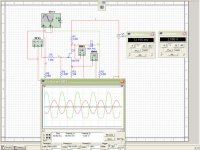
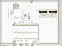
here is an example - sim:
input sinus 200mv red, output = green
with 18v ........and with 34v
with power supply at 18.5 volts and drain resistor set to 1000 ohms, the voltage on the drain of the jfet is 9.4 volts (measured between drain and ground). Onset of clipping is now 3.6volts and is symmetrical. The input signal to the pre amp is .3 volts. These voltages are measured by a meter so they are rms. The current through the drain is 8.6ma.
yes.....symmetrical clipping, drain res around 1k.........should work.
with a drain res = 2,2k psu at 18v is too low.........34v as shown in the pass schematic will fit.
here is an example - sim:
input sinus 200mv red, output = green
with 18v ........and with 34v
Attachments
Quote
"You can not expect that much usable output from this circuit.
According to Nelson's measurements (post #58 of this thread) the THD at 2V is 5%"
But I thought that line level is up to 2v...
so this pre amp is not suitable where you need to swing voltage up to 2v into a lowish gain amplifier ??
"You can not expect that much usable output from this circuit.
According to Nelson's measurements (post #58 of this thread) the THD at 2V is 5%"
But I thought that line level is up to 2v...
so this pre amp is not suitable where you need to swing voltage up to 2v into a lowish gain amplifier ??
My BoZ and BoZSE produce 17V p2p of swing before any degeneration of sine wave. I run mine on 27V. I'm using the BL series of jFets.I presume your JFET has the Idss of 9.7 mA. With 10 Ohms source degeneration the Id will be about 7-8mA.
2k2 x 7mA = 15.4V - This means that your JFET works with very low Vds and that's where the early clipping comes from.
Reduce the Drain resistor to get about 8 Volts at the Drain, but don't expect to get more than a few Volts of clean swing from that design.
Hi,
I have an orginal BOZ driving a SE MosFet Power Follower amp (which has effectively no gain). The combination provides more than enough volume on my ancient Whatmough 202 speakers of 86dB sensitivity.
My question is: Will the JFet BOZ be able to provide similar dive capability as the older BOZ? The power follower amp needs about !0V RMS to drive it.
Joe
- Home
- Amplifiers
- Pass Labs
- Jfet BOZ