From Nelson's link...
----The Plush “Pure Gain” pedal is a unique product co-designed by Nelson Pass (a noted high end audio Designer) and Andy Fuchs. It uses a unique circuit topology which uses high gain FET’s, for lowest noise and the warmest tube like sound possible. ----
----The Plush “Pure Gain” pedal is a unique product co-designed by Nelson Pass (a noted high end audio Designer) and Andy Fuchs. It uses a unique circuit topology which uses high gain FET’s, for lowest noise and the warmest tube like sound possible. ----
At the moment, it goes silent after playing for a while, so my settings must be sub-optimal. I will either have to tweak some more or use a mains driven power supply.
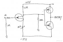
The source resistance is 2 x 10r (actual reading on my cheap dvm is 5.7r). The drain is a 10k trimpot. I have not taken a reading of actual drain resistance. I just tweaked it until i got 42 millivolts across the source resistors. That was about the only setting that gave reasonable drain voltages for both channels. This translates to 7.3mA across the source resistors. I then fiddled with the trimpots while listening to music. The sweet spot (for both channels) was actually pretty much where I had it to start with. BTW, there is a very handy Excel utility I use called Ohm's law calculator. It was a free download from P & M Services. (Saves you having to choose 10 or 100 or 1000 values in order to save yourself some maths. (Reason for choosing a 10ohm source resistor, Mr Pass?)
I tried setting equal drain voltages first, but got widely differing source currents that way, due to differences in the fets, although their idss is pretty close when measured out of circuit. I can't remember the actual drain voltages now, but they do differ a fair bit between the two channels. I will measure 2moro if you really need me to (I just got home after working a double shift). I must say that it was far more tricky to get a good setting with lower source resistance.

Hi Sam,
Hope it was helpful.
Just couldn't go to bed without fiddling with something. I checked the battery voltage and found it was around 14v. My charger is too simple, I think. It seems to drop voltage as the batteries discharge. I raised the out put on the wall wart to 12v and now they are charging at 9.2v. I need to put an LM317 before it to keep it at 9v.
Actually, I think I will eventually build a regulated supply. Maybe its time to play around with discrete regulator circuits. Anyone got any recommendations?
William.
William.
Shunty...see Choky for this one
Or just a shunt of some type...actually I would try a shunt, a series (both discrete), and a simple LM317 type regulator then sample the difference. Pair with some nice wine and make an evening of it 🙂
Cheer
James
Or just a shunt of some type...actually I would try a shunt, a series (both discrete), and a simple LM317 type regulator then sample the difference. Pair with some nice wine and make an evening of it 🙂
Cheer
James
Seems to me that it would sound like push/pull
But you know we can never tell with these simple circuits.
Mr. Pass et all - Am I correct in thinking that the original JFET BoZ is set at roughly 5mA give or take? Currently I am running mine at about 6.25mA via the CCS. I also stuck in a different (lower) resistor value and ran it up to about 7.7mA roughly. It arguably sounded a bit better with the higher current, although I was comparing them in about 5min...not ideal conditions. I don't know how far I can push these little buggers. I can generally push tubes until they glow then back off a little bit (Obviously this is not the ideal way to do things and it is not done often. Sometimes though you just the hankering to see what a part can do in the hopes you may stumble onto something special. Something you would have never found with the ruler/data-sheet/calculator, something that reaches towards audio nirvana.) With these little FET's though once pushed to hard they just say "nope" and quit, occasionally with a little puff or some heat. At least this is my experience with "sand", of course I could just have bad luck
I may have to try some FET's though as a CCS, maybe those little Zetex parts...though if I decide to pick some of them up they may find themselves used as a buffer or maybe in place of the JFET; anyone ever tried a little Zetex N-Channel in place of the SK170? Blah Blah Blah...lots of ideas and not enough time or money 🙄
Cheers
James
JPeitzman said:Shunty...see Choky for this one
Or just a shunt of some type...actually I would try a shunt, a series (both discrete), and a simple LM317 type regulator then sample the difference. Pair with some nice wine and make an evening of it 🙂
Cheer
James
look for Shiny , not Shunty
O.K., I give up. I looked for more than an hour already. Where can I find "Shiny"? (I hope it is a lot simpler than "Shunty"!) I am not good at complex stuff (hence my interest in Jfet BOZ).
The original idea was to use batteries, but my 9v Ni-mh are running down too fast and I can't afford to buy more batteries. I already have 2A 24v transformer and a super bridge I built with soft recovery diodes for a valve preamp. I am just concerned about noise. Is anyone using regs on their jfet BOZ?
The original idea was to use batteries, but my 9v Ni-mh are running down too fast and I can't afford to buy more batteries. I already have 2A 24v transformer and a super bridge I built with soft recovery diodes for a valve preamp. I am just concerned about noise. Is anyone using regs on their jfet BOZ?
hihopes said:O.K., I give up. I looked for more than an hour already. Where can I find "Shiny"? (I hope it is a lot simpler than "Shunty"!) I am not good at complex stuff (hence my interest in Jfet BOZ).
The original idea was to use batteries, but my 9v Ni-mh are running down too fast and I can't afford to buy more batteries. I already have a25VA 24v transformer and a super bridge I built with soft recovery diodes for a valve preamp. I am just concerned about noise. Is anyone using regs on their jfet BOZ?
http://www.diyaudio.com/forums/sear...63990630&sortby=lastpost&sortorder=descending
Thanx. It only took another 20 minutes of wading through these threads to find a schematic. I had thought there was a thread for it, or a manual or something.
gl said:Nelson,
So what's Colin's opinion of this pedal? Does he use one?
Graeme
Hi Graeme, this is Colin.
Yes, I have used the pedal, and it sounds great!
I'm probably going to order up a couple more for my friends as well.
I run my telecaster through the straight gain pedal into my Blues Junior.
To be honest I'm not sure someone of my skill level deserves such good tone. 🙂
hihopes said:Thanx. It only took another 20 minutes of wading through these threads to find a schematic. I had thought there was a thread for it, or a manual or something.
http://www.diyaudio.com/forums/showthread.php?postid=1588700#post1588700
sort of manual .......... as close it can be ...... 😉
TheseGoToEleven said:
Hi Graeme, this is Colin.
.......
Little Papa 😀
nice to have you here .........
( be careful - we are here sort of Adams Family
 )
)- Home
- Amplifiers
- Pass Labs
- Jfet BOZ