Finished the boz-j, but it's not working. Loud hum/buzz in both channels; no music at all. Will have to troubleshoot later when i have more time.
Check parts orientation, values and connections - actually, taking it apart and building it again carefully might be a quicker solution 😉
check three voltages on your jfet legs...I don't remember what vpinch was, but I bet you voltages are off
I think I made a big mistake. I"m using the original schmatic presented by Mr Pass.
I used a positive voltage...does the 2sk170 require negative voltage?
The rating is -40v max.
Tell me I just made a dumb a** blunder like that?
I used a positive voltage...does the 2sk170 require negative voltage?
The rating is -40v max.
Tell me I just made a dumb a** blunder like that?
Vdi_nenna - just to make sure, pray tell exactly what is the schematic you are trying to build (post number, link....) and then we'll now for sure what's the optimal solution 🙂
...what is the schematic you are trying to build (post number, link....)
This thread, first page, second post by Mr Pass.
Originally, 35v was suggested, later 16v was found to be optimum.
I used a LM317 and used an online calculator to find the values for +16v, but in practice, the voltage came out to 14.35v with a 20v torodial and bridge.
Fine, I would change that later, assuming +14v was enough to run the circuit for now.
BTW- I do have some 2SJ74 on hand, if the opposite was required.
Last edited:
Simetrix says 14.5v is not enough voltage. When simming 14.5v, drop the Drain resistor to 820 and I get a sine wave. Projected 10mA current through jfet. Increase source resistance to 33ohms and current drops to 6.5mA.
Last edited:
Really? That's pretty cool. Well, I'll have to find what values will get me to 16v.
Thanks Carp.
Vince
Thanks Carp.
Vince
@vdi_nenna:
14V, 16V - neither will give you really usable swing - if you prefer that version you'd better stick to orginally proposed 35V PS voltage...
14V, 16V - neither will give you really usable swing - if you prefer that version you'd better stick to orginally proposed 35V PS voltage...

14V, 16V - neither will give you really usable swing
That's too bad, I thought I read that 16v was optimum?
Anyway, luckily the transformer was only $13 new! 🙂
Thanks very much for you help everyone!
 you are.... unique !
 Hi!
Many time I saw 25K trimmer pot in the input. Is it for volume pot??
What could be the best value for a potenciometer?
Tyimo
Many time I saw 25K trimmer pot in the input. Is it for volume pot??
What could be the best value for a potenciometer?
Tyimo
I have made a sweet spot search on one of these small things and found it around 16.3V for both channels using Nelson's first schematic.
I has no problem swinging 1V rms, which is the needs in its current application.
If you need more swing at approximately the same supply voltage you must change the drain resistor with a CCS.
I has no problem swinging 1V rms, which is the needs in its current application.
If you need more swing at approximately the same supply voltage you must change the drain resistor with a CCS.
I am using the circuit nelson posted on the first page with a modified BOZ PSU circuit. It uses the IRF610 regulator and zeners to put out 18V - 4V(regulator) = 14V. The amp is exactly as posted on page 1. It uses just positive voltage - I am using a 19V dell laptop supply to the zeners (9V x 2)
Sounds excellent with the F5.
Sounds excellent with the F5.
Last edited:
If 1Vrms suits your needs - fine....
I has no problem swinging 1V rms, which is the needs in its current application...

Driving an F5 to full power takes more than 2.5V rms...
That might help but you'd have to find a way to restrain the gain - someone used Drain-to-Gate NFB and reported fine results.If you need more swing at approximately the same supply voltage you must change the drain resistor with a CCS.
here is a picture.Many time I saw 25K trimmer pot in the input. Is it for volume pot??
What could be the best value for a potenciometer?
What is that trimmer pot for???
Grets:
Tyimo
Attachments
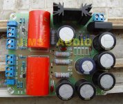
If I were to guess, they're there (left and right channel?) to adjust input. This way, it's harder to overdrive the circuit with a hot signal. I use it to get my amp into it's best position (sonics wise) because my friends may not know how.
What is that trimmer pot for???
It's a volume control, but the pots in the photo are more like an attenuator to limit peak input.
Sort of set and forget...maybe, not sure?
Last edited:
- Home
- Amplifiers
- Pass Labs
- Jfet BOZ