Found this thread that corroborates these ideas. http://www.diyaudio.com/forums/solid-state/166099-accurate-measurement-jfet-gm.html
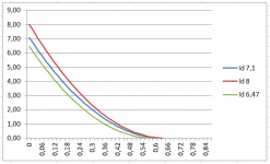
Used a 1M63 rsistor istead of 1M and got the following results for 2SK170BL:
Idss 6.47mA > Vp -0.59V
Idss 7.10mA > Vp -0.64V
Idss 8.00mA > Vp -0.65V
Not at all what I was expecting and not comparable to the pdf specs...
Used a 1M63 rsistor istead of 1M and got the following results for 2SK170BL:
Idss 6.47mA > Vp -0.59V
Idss 7.10mA > Vp -0.64V
Idss 8.00mA > Vp -0.65V
Not at all what I was expecting and not comparable to the pdf specs...
Attachments
Your post41 shows why high Idss BL grade sk170 should not be used in low Vds applications.
Can you confirm the formulae in post42? What is V? what is Vid?
Can you confirm the formulae in post42? What is V? what is Vid?
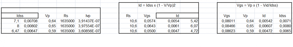
Id = Idss x (1 - Vgs/Vp)2
Vgs = Vp x (1 - √(Id/Idss))
Would you pleas explain what you mean on post 43 ?
Vgs = Vp x (1 - √(Id/Idss))
Would you pleas explain what you mean on post 43 ?
Found this thread that corroborates these ideas. http://www.diyaudio.com/forums/solid-state/166099-accurate-measurement-jfet-gm.html
Used a 1M63 rsistor istead of 1M and got the following results for 2SK170BL:
Idss 6.47mA > Vp -0.59V
Idss 7.10mA > Vp -0.64V
Idss 8.00mA > Vp -0.65V
Not at all what I was expecting and not comparable to the pdf specs...
Looking at the 2sk pdf I see that for any Idss, Vp is always higher than -0.5V
Using the high Rs technique I found much lower values (Higher in modulus).
Does that mean the high Rs tech is not fiable... or does it depend on Vdd ? (I am using a 9v batt)
For good performance the jFET should operate with Vdg & Vds > 2 times Vp.
If higher Idss jFETs are used then 2 times Vp becomes very difficult to achieve.
Low Idss and high gm make this relatively easy.
If higher Idss jFETs are used then 2 times Vp becomes very difficult to achieve.
Low Idss and high gm make this relatively easy.
For Idss 8mA I have Vp = -0.65V
2 times Vp should be -0.325V or are you meaning 2 x |-0.65| = 1.3V ?
2 times Vp should be -0.325V or are you meaning 2 x |-0.65| = 1.3V ?
For Idss 8mA I have Vp = -0.65V
2 times Vp should be -0.325V or are you meaning 2 x |-0.65| = 1.3V ?

2 x (-0.65) = -1.3
!!!
So Vds should be > 1.3V in this case.... I read 7V in my simplistic first stage ... can not see the issue
and change to a low gm device selected to have a high Idss and suddenly even your 7V for Vds compromises the jFET operation.
As an example look at the DCB1, there are jFET in there with operating Vds in the range 600mVds to 10Vds
One can and should select different jFETs with different gm and different Idss for the various locations.
As an example look at the DCB1, there are jFET in there with operating Vds in the range 600mVds to 10Vds
One can and should select different jFETs with different gm and different Idss for the various locations.
Last edited:
After some reading I get the idea that increasing Vds might provide some increase in imaging and CMR.
For a 2sk170 I found Vds to be better between 7 and 11volts.
Anyone ?
For a 2sk170 I found Vds to be better between 7 and 11volts.
Anyone ?
Great thread. Enjoyed reading it. I have learned more about jfets now😉. I have resurrected my pacific phono stage and it sounds great. With some more mods with latest knowledge should be even better.
PS I always had trouble with parasitic oscillations with this cct due to high gain. But gate stopper resistors saved the day. I am a bit surprised I don't read more of others having this hassle 😕 but anyway.🙂
cheers,
Pauly.
PS I always had trouble with parasitic oscillations with this cct due to high gain. But gate stopper resistors saved the day. I am a bit surprised I don't read more of others having this hassle 😕 but anyway.🙂
cheers,
Pauly.
basically sounds like mass distortion.
there is so much gain and open bandwidth that high frequencies begin to feed back positively creating an oscillator. some of the stuff and mixed products are in the audio band. it's awful. Also depending on what wires sit where and what else is to chance it may go , be minimal, or be chronic. very frustrating when a lovely sounding pre amp is in there somewhere.
p.
- Status
- Not open for further replies.
- Home
- Design & Build
- Parts
- JFET Basics