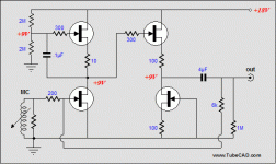
This is a very interesting post about a Jfet Aikido version:
http://www.diyaudio.com/forums/pass-labs/103050-jfet-boz-11.html#post1230020
The author says the sound is no good as tube version.
How about improvement ?
http://www.diyaudio.com/forums/pass-labs/103050-jfet-boz-11.html#post1230020
The author says the sound is no good as tube version.
How about improvement ?
The circuit shown does not embody the Aikido principle. The filtering done by C2 means the power supply noise injected anti-phase by Q3 does not match, and therefore does not cancel. I am also sure that having an active current source to load the first gain element will sound different than a resistive source (as shown here).
I don't agree, perhaps the circuit is correct, because on R3 you have 1/2Vcc + supply ripple.
As you inject on gate of Q3 the same 1/2Vcc + supply ripple, on R3 you cancel.
Instead, I agree on an active current source to load the first gain element.
I'll simulate it.
Thanks
As you inject on gate of Q3 the same 1/2Vcc + supply ripple, on R3 you cancel.
Instead, I agree on an active current source to load the first gain element.
I'll simulate it.
Thanks
Excuse me for my mistake, is OK this:
"As you inject on gate of Q3 the same supply ripple, on R3 you cancel"
Now, I think is better to shunt R11 (100k) as original circuit JFET Aikido by tube cad.
"As you inject on gate of Q3 the same supply ripple, on R3 you cancel"
Now, I think is better to shunt R11 (100k) as original circuit JFET Aikido by tube cad.
This is my Aikido_jfet version:
http://img535.imageshack.us/img535/8338/aikidojfet1nappi84.jpg
It simulates very good.
LTSpice Distorsion is very low, 0.06% with 1Vpp input and 6Vpp output:
Harmonic Frequency Fourier Normalized Phase Normalized
Number [Hz] Component Component [degree] Phase [deg]
1 1.000e+03 3.010e+00 1.000e+00 -178.47° 0.00°
2 2.000e+03 1.942e-03 6.454e-04 -102.11° 76.36°
3 3.000e+03 2.845e-04 9.452e-05 -174.87° 3.60°
4 4.000e+03 4.072e-06 1.353e-06 90.26° 268.73°
5 5.000e+03 1.382e-06 4.592e-07 -94.00° 84.47°
6 6.000e+03 2.127e-06 7.069e-07 87.43° 265.90°
7 7.000e+03 1.467e-06 4.875e-07 -104.25° 74.22°
8 8.000e+03 2.102e-06 6.983e-07 86.96° 265.43°
9 9.000e+03 1.465e-06 4.868e-07 -108.63° 69.84°
Total Harmonic Distortion: 0.065227%
You can use no feedback but you gain much more.
It saves Aikido principle and could sound as Tube version but I haven't try it.
Good 2011!
Hello,This is my Aikido_jfet version:
http://img535.imageshack.us/img535/8338/aikidojfet1nappi84.jpg
It simulates very good.
LTSpice Distorsion is very low, 0.06% with 1Vpp input and 6Vpp output:
<snip>
You can use no feedback but you gain much more.
It saves Aikido principle and could sound as Tube version but I haven't try it.
Good 2011!
Please tell us more?
How did you pick the operating voltage?
Do you recommend any IDSS matching? If then what milliamp value?
How did you pick the resistor values?
I know this stuff for tubes but not these fangled JFETS!
DT
All just for fun!
- Status
- Not open for further replies.
- Home
- Amplifiers
- Solid State
- Jfet aikido
