oops,
Vre is 15 to 25mV for optimum ClassAB bias.
D.Self calls this ClassB and he suggests Vre=25mV+-2mV depending on Re. i.e 0.026V
Edit:
my oopsie removed
Vre is 15 to 25mV for optimum ClassAB bias.
D.Self calls this ClassB and he suggests Vre=25mV+-2mV depending on Re. i.e 0.026V
Edit:
my oopsie removed
In addition to the above mentioned barrredboss, Digikey, Newark and Mouser both have some. Also try M & M Metals, Wakefield or Aavid Thermalloy.
Apexjr.com often has suitable sinks. If you don't see what you like on the website, give Steve a call. He usually has a few pieces of something suitable not shown on the website.
From pricing I have seen, if you want new sinks in the traditional wide extrusion/fins vertical form, Conrad's MF350 profile is the way to go even considering shipping them via air. Last I checked that amounted to about $100 per sink, a heck of a lot better than Digikey.
AndrewT said:oops,
Vre is 15 to 25mV for optimum ClassAB bias.
D.Self calls this ClassB and he suggests Vre=25mV+-2mV depending on Re. i.e 0.026mV
Thanks Andrew. I assume that you meant to type Vre= 0.026 V 😉
Sorry for scaring anyone by shifting an order of magnitude. That amounts to a 30-40W per channel. Not too hard to handle, but higher than most commercial prodcuts are biased.
BobEllis said:
Pass' Aleph series use the source resistors in the active current sources to set the bias.
Hee hee, that's where my misconception coming from 🙂 Any suggestion what to change if I want to bias a little hotter?
BTW, can someone help me to confirm whether the value of the R3 and R22 (sorry I had typo in my previous post) is correct or not with respect to the toroid that I have? Basically, we want to bias approx 8.2ma across T3 and T5, correct?
Thanks!!
Judiciously adjust P1 to get the bias you desire.
Go in small steps, let it settle for 15 minutes or more before adjusting again. Keep an eye on heat sink temp.
Measure the current either as leach suggests by replacing a rail fuse with an ammeter or measuring the voltage across the emitter resistor.
Yes, your math is correct for the stated rail voltage.
Thanks a lot, Bob!!
You now know what I will be doing in Thanksgiving.
No, I am not roasting my bird with the Leach 🙂
You now know what I will be doing in Thanksgiving.
No, I am not roasting my bird with the Leach 🙂
Will this amp run in class A without problems or should things be designed that way from the beginning. I am running about 1 amp per rail on my Leach. Is there any chance of a problem with this much bias?
Tad
Tad
The issue with running class A is heat. Specifically, keeping the junctions at reasonable temperatures. Most output devices are rated at 150 C. Aim to keep the junctions under 100C for reliable operation.
The only potential downside with this design is that the output devices are close together, and may run a little hotter on the same heat sink compared to spread outputs.
Nelson Pass has a good treatise on calculating required heat sinking in his A75 articles at www.passdiy.com. The nutshell version is that the thermal resistances of the output device junction to case and through the isolator are in series, so they add. Multiply the device dissipation by the sum of the thermal resistances to get the rise above the heat sink temperature. The total dissipation in the output stage multiplied by the sink thermal resistance determines the temperature rise above ambient.
In Tad's case:
The MJL4281 is specified with a thermal resistance junction to case of .54 degrees per watt. If running 60V rails and 1A total bias, that means each device is dissipating 12W and the junctions will be 6.5 degrees above the case temperature.
The case then has then pass the heat through the isolators to the sink. Assuming that you are using mica or silpads, there is roughly another 1.4 deg/W, meaning that the output device side of the isolator is 16.8 degrees hotter than the heat sink side.
So we have the junctions 23.7 degrees above the heat sink temperature.
Measure the heat sink temperature near the center of one of the strings of output devices. Add the temperature rise and see where you stand. (this way you can determine the real temperature coefficient of your heat sinks in your installation rather than estimate based on empirical data)
If your rails are other than 60V, determine the actual dissipation and multiply by 1.94 deg/W to get the rise above sink temperature.
Another thing to watch is the room temperature in summer compared to what you'll have today. Higher ambient temperature will increase the junction temperature.
BobEllis said:roughly another 1.4 deg/W
Way too high.
You can easily make output devices eat +30W each by blueprinting them, for details see e.g. Roddy-E's ESP.
Several commercial manufacturers use Aluminum Oxide insulators, Audionet for instance.
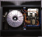
Example piccy :
400W in Class AB and 200W in Class A from 7 pairs of output devices spaced half an inch apart (Seifert KL274 heatsinks, 20" wide and 0.125C/W each)
Attachments
That number came from data sheets and other web sources saying .7 into the isolator and .7 off = 1.4 across an isolator.
In an experiment with a shop grade thermometer a couple years ago I measured about .8 deg/W across a silpad. I touched the probe to measure the temperature of the sink right next to a Fairchild IRFP240 and then the bit of exposed metal back near the mounting hole. Aluminum oxides seem to be about 1/10 that.
I figured leaning towards the conservative was the way to go for the less experienced of this thread's readers. Glad to have another perspective, Jacco.
I always liked the neat layout of using aluminum oxide insulators, but they cost almost as much as the output devices if not more. Even silpads are overpriced in my opinion. Would not a very thin film of high grade silicone adhesive work as well as the silpad. You could lay it out on a piece of glass with a silkscreen roller and peel it off once it had cured. Always looking for a way to stretch my hobby dollars.
Has anyone yet found a really low price in a to-247 configuration? Last time I checked they were about 7.00 each for the aluminum oxide ceramics. They do look cool though -- no pun intended.
Tad
Has anyone yet found a really low price in a to-247 configuration? Last time I checked they were about 7.00 each for the aluminum oxide ceramics. They do look cool though -- no pun intended.
Tad
Tad, this time it's you whose memory is off by an order of magnitude. 
Mouser has these TO-218/TO-247/TO-3P Aluminum Oxide Isolators for $0.70 each or less.
You could also try 1" Kapton tape at $67.81 for a lifetime supply (36 yards). Just few dollars more expensive than 100 aluminum oxide isolators and even lower thermal resistance and easier mounting. Cut two strips long enough to cover the output and driver mounting areas, stick them down and mount the amp. I haven't done it yet, but with the number of amps in my pipeline...
Bob,
The only place I could find them in the past was a European supplier -- Elma I think -- in the configuration I needed.
However, Since your last post I have ordered my needed share from Mouser. Like I need another Leach amp. Backordered of course. Wish I had added them to my Friday order. UPS is the only one making money these days.
And thanks again, Tad
why Is so Important to supply this amp from at least 2 x 40 Vac transformer
could I use at least 2 x 35 Vac transformer
could I use at least 2 x 35 Vac transformer
Does anyone want to share this kapton tape with me? This is the same kapton tape that Bob referred to. It will be $20 per roll + shipping and a padded envelop.
pchw said:Does anyone want to share this kapton tape with me? This is the same kapton tape that Bob referred to. It will be $20 per roll + shipping and a padded envelop.
i am interested in two rolls shipping to manila, philippines, please...
Cool, I will BIN the kapton tape from ebay and post here when I receive it.Tony said:
i am interested in two rolls shipping to manila, philippines, please...
pchw said:Does anyone want to share this kapton tape with me? This is the same kapton tape that Bob referred to. It will be $20 per roll + shipping and a padded envelop.
I will take one (1) also!

Thanks for offering Fred.

Acknowledged!dudaindc said:
I will take one (1) also!
Thanks for offering Fred.
Thus far, 6 are reserved including mine, 3 remain unclaimed.
Thanks!!
- Home
- Group Buys
- Jens Rasmussen Leach clone group buy