Where do you want to place the thermal diodes?
1) On output board
2) On seperate board
3) Somewhere else?
\\\Jens
I like the current separate board arrangement for the compensation diodes. It's awfully convenient.
I agree with separate diode board. I understand the cost impact. I think the flexibility is worth it.
Re: Not a trick question
How about gluing diode connected sot23 transistors to four of the collector leads of the output transistors?JensRasmussen said:Hi,
Where do you want to place the thermal diodes?
1) On output board
2) On seperate board
3) Somewhere else?
\\\Jens
Can you rotate the drivers into that open space below to allow space for heat sinks? It looks like there's room to lay them flat or maybe use a small vertical sink. Either way - I have lots of both 😉
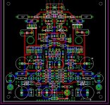
I presume that the holes near C2 and C19 are for access to the temperature compensation diodes. Perhaps you could provide acces on the output board.
I envision mounting the front end board above the output board so if either the mounting hole align or there is a set of holes on the output for mouting the end it would be great.
Nice to see you "working" in public again Jens. 😀
//Bob
Jens,
I'm glad to see the design head in this direction! 😉
Thanks for all of your hard work with this. I think it will make it an infinitely more useful design for most people.
I think with separate output boards, we will no longer need the access hole in the main/driver board for TC diodes.
Thanks,
Donovan

Single sided front end
Hey all,
Thanks for the patience on this one....
I tired to go for a single sided front end last night.... is this something that you would like also?
Edit: file upload is not working at the moment... stay tuned
\\\Jens
Hey all,
Thanks for the patience on this one....
I tired to go for a single sided front end last night.... is this something that you would like also?
Edit: file upload is not working at the moment... stay tuned
\\\Jens
rotate the drivers
Very fast move Jens.
Maybe it is better for stability to have the drivers on one heatsink, you can rotate one driver so that they have the same direction. Also you need a little more space then between the rest of the components.
good job!
Loek
Very fast move Jens.
Maybe it is better for stability to have the drivers on one heatsink, you can rotate one driver so that they have the same direction. Also you need a little more space then between the rest of the components.
good job!
Loek
Look ahead to the outputs
I think I'll be interested in additional output boards. Anybody else?
I think I'll be interested in additional output boards. Anybody else?
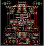
Re: Single sided front end
JensRasmussen said:Hey all,
Thanks for the patience on this one....
I tried to go for a single sided front end last night.... is this something that you would like also?
\\\Jens
Attachments
Jens,
It looks like you were able to make it single sided without giving up anything, so I think it's a good idea.
What about moving C2 and C15 down closer to the predrivers, so that there would be a little more room for heatsinks on the drivers?
Other than that, I think it looks good and should save everyone some money being single sided.
Thanks!
Donovan
dudaindc said:Landoctor
Were you able to get the heatsinks?
Cheers!

Duda,
Yes, I was. Thanks. 🙂
I see you are looking at the others. Those look nice also. 🙂
I like that layout. How is the tie in from this board to the output board going to be configured. Hard wire, screw terminal, or din rail?
Real nice. Tad
Real nice. Tad
from what i gather, the sections are still joined, separation of the boards are done by the user..
Both Jens' projects, the 10 transistor Leach Amp and the "Leach Super Amp" are being designed with separate front end boards. Looking at both wiki pages, there are a total of about 150+ people who want boards for both amplifiers. Have we considered the value in using the Super Amp front end board for both projects? Cascode voltage stages tend to sound very good. Audio Research's and Nelson Pass' designs have used cascode front ends to great sonic advantage. I question the desirability of a cascode output stage from the point of view of sound quality. Mr. Pass has not repeated this arrangement in his latest designs. He was not impressed with the sound quality of the cascode output stage VS a single devices in parallel between the supply rails and the load. He used the cascode configuration, as did several others, to overcome the lower voltage ratings and SOAs of transistors available at the time. This is no longer necessary using modern output transistors. Everything I have heard and read about the sound quality of the Low TIM Leach Amp VS the Leach Super Amp indicates that the Super Amp is more dynamic. This is primarily due to its cascode front end. Its cascode output stage keeps it from being a truly super amp sonically. I suspect that retaining the cascode front end, while employing the final output stage of the low TIM amplifier will yield the best variation yet of the Leach design. The output configuration could be left to the builder to select plastic outputs, metal case outputs, etc. A superior front end board incorporating Jens’ latest suggestions only based on the Super Amp might give all builders the chance to configure whatever amplifier they wish.
I suggest this thought for others to comment upon. We could make one group buy if we did this for at least 150 boards. ---- HK
I suggest this thought for others to comment upon. We could make one group buy if we did this for at least 150 boards. ---- HK
come to think of it, the leach super amp front end board can be be configured as lo-tim board if the builders wishes....i've seen it done on the original leach lay-out...yes, why not?😀
I agree that the Leach Super-Amp front end, with multiple output stage possibilities would satisfy most all builders by allowing them their choice of which amp to build. It would also allow us to pool our orders and make the board cost much less for everyone.
I would vote for a no holds barred version of the Super-Amp frontend with detachable output boards for at least 5 pairs of output devices each. That way people could have the flexibility to build whatever they want, and the logistics of handling the GB would be much simpler.
Donovan
I would vote for a no holds barred version of the Super-Amp frontend with detachable output boards for at least 5 pairs of output devices each. That way people could have the flexibility to build whatever they want, and the logistics of handling the GB would be much simpler.
Donovan
Quite astute observation on your part Lesherons. I am in for 6 boards in whatever configuration we choose. I really like this idea you have proposed. Kudos.
My only suggestion is that a suitable arrangement be implemented on the pcb for very NEAT and substantial connection of wires from frontend to output board after separation. We could also make a completely separate frontend board and output component board not needing to be cut. It also might be cheaper. This would give the builder the option of purchasing the number of individual output boards needed for there particular amp requirements. Tad
My only suggestion is that a suitable arrangement be implemented on the pcb for very NEAT and substantial connection of wires from frontend to output board after separation. We could also make a completely separate frontend board and output component board not needing to be cut. It also might be cheaper. This would give the builder the option of purchasing the number of individual output boards needed for there particular amp requirements. Tad
- Home
- Group Buys
- Jens Rasmussen Leach clone group buy