Hard to believe that hand-drawn schematics exist instead of blueprints. May lead to QC problems. Can remember when Mr. Carver released detailed schematics of all of his magnetic amplifiers; including the Lightstar. I also requested the schematic of a STASIS amp from Mr. Pass while at Threshold, and was sent to me gratis. Audio legends have different practices. May need to X-ray the JR modules at a friendly dentist.By currently models, but not from this old stuff. In the meantime I have heard, that the only reason for the not available schematics would be the fact, that there are only hand-sketched drawings present, and unfortunately very hard to find in the very large quantities of the archived documents.
But now more questions:
1) some parts of the external power supply envelopes of this models goes very hot and other remains cold.
What could be therefore the reason? Maybe because the current consumption of the modules depends on the year of manufacturing?
2) The voltage gain factor of the preamp is different by the same configuration of jumper. Are there in the modules also different parts for the feedback resp. gain determination?
A detailed schematic diagram of all exist variantes from the modules would be very helpful.
Fo me probably it is the same work than by the shed (embed) modul from John Curl's head MC amp JC-1DC - go toHard to believe that hand-drawn schematics exist instead of blueprints. May lead to QC problems. Can remember when Mr. Carver released detailed schematics of all of his magnetic amplifiers; including the Lightstar. I also requested the schematic of a STASIS amp from Mr. Pass while at Threshold, and was sent to me gratis. Audio legends have different practices. May need to X-ray the JR modules at a friendly dentist.
Mark Levinson JC-1DC
They do seem to have a SYMEF variant in there 😀
I have a pdf article by W. Marshall Leach, Jr. entitled 'Head Amps for MC cartridges'; which shows schematics like that of JC-1DC.Fo me probably it is the same work than by the shed (embed) modul from John Curl's head MC amp JC-1DC - go to
Mark Levinson JC-1DC

Bradford-Electronics-Incorporated. (eaten by KOA speer)
The one North-East of the center reads Corning Glass Works.
The one North-East of the center reads Corning Glass Works.
Thank you for this information.Bradford-Electronics-Incorporated. (eaten by KOA speer)
The one North-East of the center reads Corning Glass Works.
Are there a possibility to find faulty modules somewhere?
In this case I would purchase it for creating the schematic and check the current-flow - next time I will get two parts of this preamp model for service - one runs hot after a short time after switch-on (only power supply - hum and noise from one channel by listening) and at one device the voltage gain of the line stage module for the inverted mode is too low at one channel.
To perform a comparison between the required values of all parameters (unknown) and the presently ones a schematic include p-spice simulation is unavoidable.
To analyze the internal structure I want faulty modules - there are two different for the phono and the line stage.
Last edited:
Are the modules dead.? Google shows that heating the encapsulating epoxy above its glass transition temp may/will soften it for removal. Can you identify the function of the pins/leads for testing on the bench. My guess that in the long range, you may be able to make your own module [from established schematics] and replace the defective one. The reference by ramallo has rich detail for the phono stage, and the line level modules are said to be like that of the power amp[pseudo schematic] ;but with much lower rail voltages.This Thread exist already and is closed:
http://www.diyaudio.com/forums/solid-state/199705-jeff-rowland-coherence-one-schematic.html
I want to have the schematics of this discrete jFET operational amplifiers:
1) Phono Amp Low Level
2) Phono Amp High Level
3) LINE AMP INVERTING
4) Line Amp NON inverting
Who can help?
The modules are similar to those from JC-2 (John Curl, Mark Levinson)
JC-2(220V»ÅÍÍ¡Ë Mark Levinson HiFi-Do McIntosh/JBL/audio-technica/Jeff Rowland/Accuphase
Tg of the modules epoxy maybe less than 100 Celsius. May put the tip of a hot soldering iron to it and probe it!
Last edited:
Tg of the modules epoxy maybe less than 100 Celsius. May put the tip of a hot soldering iron to it and probe it!
Nope. Been there, done that. Still got the burn marks on the carpet to prove 🙂
Deadly chemicals were no use either.
A hot air station set to 500C allowed me to remove tiny flakes of epoxy using a chisel. Took me two full days. Or three.
Thank you for this valuable info. The manufacturer has done a great job protecting the circuit/schematic. The circuit inside the module cannot be repaired even by the manufacturer. Thus, the manufacturer implicitely suggested replacing the faulty module at an accredited service facility. How much will a brand new module cost for a do it yourself installation? Is a faulty ML or JR preamp worthy of repair?Nope. Been there, done that. Still got the burn marks on the carpet to prove 🙂
Deadly chemicals were no use either.
A hot air station set to 500C allowed me to remove tiny flakes of epoxy using a chisel. Took me two full days. Or three.
JR will be happy to advise you regarding cost and availability. Off the top of my head i would guess around $400 per module. Occasionally modules seem to appear on ebay...
Thank you for the info. I do not have a JR or an ML preamp;but I hope your findings are useful to tief..and other DIYers to pursue their best solution.JR will be happy to advise you regarding cost and availability. Off the top of my head i would guess around $400 per module. Occasionally modules seem to appear on ebay...
analog_sa. Encapsulation may have the side effect of managing heat and its gradients in the organic block. The heat generating devices are smothered, and thermally claustrophobic. Unless the cured polymer has an adequate thermal conductivity to move heat away from the devices, then hot spots may develop to eventually cause their failures, and quiescent point drifts requiring DC servos as noted.
This is only applicable in such cases where a second board above the first is in use inside of the same encapsulating epoxy module.Thank you for this valuable info. The manufacturer has done a great job protecting the circuit/schematic. The circuit inside the module cannot be repaired even by the manufacturer. Thus, the manufacturer implicitely suggested replacing the faulty module at an accredited service facility. How much will a brand new module cost for a do it yourself installation? Is a faulty ML or JR preamp worthy of repair?
Otherrwise not, because I don't have it open.
The access from the solder side of the PCB (by sand e. g.) is completely sufficient for me to find out the circuit topology (and routing of the copper rails) so as for replace of any part.
Nevertheless - it would be better, to have the schematics of the modules previously.
P.S.
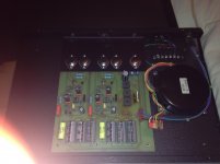
The first preamplifier of this model has arrived to investigate. The cable connector from the toroidal transformer to the PCB pins of the power supply device so as the PCB-pins and PCB itself have been very strongly superheated (sound check in this condition isn't possible without the risk of additional damages).
This means, the superheated region of the PCB must necessarily be removed with help of drilling mashine and cut-off wheel (hard to believe an a preamp in this price range - for doing this I will create images of this desaster previously, probably after Christmas).
Why the hell the transformer was not soldered directly with the PCB rails ???
The reason for the overheating are resistances between the male and female connectors - also good known at the old versions from Electrocompaniet's Ampliwire 100.
About
http://sorscha.xs4all.nl/Shop/catalog/images/aw100-2.jpg
you will find the PCB male connectors on left site. This are the connectors to the power supply - also very strongly superheated in some cases.
Last edited:
tiefbassuebertr. Granted that you are able to sand the epoxy on the solder side of the module to expose the pcb so as to read the copper traces. Can you tell whether the component side is or not embedded in a block of epoxy polymer all the way to the curved/top side of the module? I think analog_sa may have an answer to that. Suppose the epoxy polymer is all the way through. It will make it almost impossible for you to replace a faulty component. My guess is that the components are fully embedded on purpose so as to operated the semis as hot as possible [no free air cooling] but without infringing on their SOAs. Thus one gets the best sound from the module.
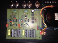
burned connectors and burned PCB area
If these modules will be rebuilt from me, there are no embedded versions.
The attached images are the supplement to my previous post.
Is there any evidence to this estimate somewhere? My suppose is no. The best sounded components I know are such with not embedded parts.tiefbassuebertr. Granted that you are able to sand the epoxy on the solder side of the module to expose the pcb so as to read the copper traces. Can you tell whether the component side is or not embedded in a block of epoxy polymer all the way to the curved/top side of the module? I think analog_sa may have an answer to that. Suppose the epoxy polymer is all the way through. It will make it almost impossible for you to replace a faulty component. My guess is that the components are fully embedded on purpose so as to operated the semis as hot as possible [no free air cooling] but without infringing on their SOAs. Thus one gets the best sound from the module.
If these modules will be rebuilt from me, there are no embedded versions.
The attached images are the supplement to my previous post.
Attachments
Last edited:
Is there any evidence to this estimate somewhere? My suppose is no. The best sounded components I know are such with not embedded parts.
If these modules will be rebuilt from me, there are no embedded versions.
The attached images are the supplement to my previous post.
Hello tiefbassuebertr. I hope that you are having a joyful Christmas. Thanks for the pics. This question persists. Is the component side of the module embedded or not? Will it be possible to slice off a small surface of the top of the module to expose its underlying belly? A shallow and sizeable drilled hole may be enough to peek inside the component side.
Hypothesis on my part regarding embedding components to give a better sound. Very fine and high purity sand or like with a poor thermal conductivity maybe used to test this hypthesis..
This question persists. Is the component side of the module embedded or not?
Yes, it is entirely embedded. The hollow shells have been filled with epoxy and the populated board added on top, component side down.
As for the beneficial effects - i see them mostly as supporting the egos of the designers. A very long time ago i have made my own experiments with potting. It obviously modifies the dielectric and vibrational properties of the boards, where the air dielectric is replaced with epoxy and the generally random vibrations of each component are unified. Soundwise this didn't do anything good.
It is also extremely unfair to sell such unserviceable equipment. In the long term is is always the consumer who pays the price for such shortsightedness.
Same is true of others like the bankrupt Halcro who kept erasing semi designations.
Thanks analog_sa for the detailed info. Thus, it will be a challenge for tiefbassuebertr to repair the module. I hope that you are having a joyful holidayYes, it is entirely embedded. The hollow shells have been filled with epoxy and the populated board added on top, component side down.
As for the beneficial effects - i see them mostly as supporting the egos of the designers. A very long time ago i have made my own experiments with potting. It obviously modifies the dielectric and vibrational properties of the boards, where the air dielectric is replaced with epoxy and the generally random vibrations of each component are unified. Soundwise this didn't do anything good.
It is also extremely unfair to sell such unserviceable equipment. In the long term is is always the consumer who pays the price for such shortsightedness.
Same is true of others like the bankrupt Halcro who kept erasing semi designations.
"Let's make things better"
I have create the schematic for the power supply include several voltages and current flows (measuring include the preamp devices in operating mode).
Philips starts a "Consistent Global Presence" (actually a slogan) in the 90’s:
“Let’s make things better”
I now have the same train of thought.
Some choices of transistors for me are suspect resp. incomprehensible in order to the necessary current head room. Particularly the 2N3055 and MJ2955.
Whether too much whiskey bottles could have been present during the circuit design?
Therefore the question:
How can one make things better ?
Thanks for advices.
Attachments
Last edited:
- Home
- Amplifiers
- Solid State
- Jeff Rowland Coherence 1 - Schematic for the Modules wanted