post11 in 3 way front loaded horn helpThis is what a bass stand horn is like.
http://www.diyaudio.com/forums/multi-way/175148-3-way-front-loaded-horn-help-2.html
mentions "stand" type.
Does Jmmlc mean one can stand something on top of the horn box?
Does that make a bass stand horn?
AndrewT,
I don't have the time to hunt for the link, but JMLC designer stated having one level type bass stand horns were more acceptable, so that someone could stack their speakers on top or other home furniture. I have seen a photo of someone with a piano on top etc...
The drivers could be time aligned with their magnet voice coils. However, I find the full height bass horns produce pipe organ music more authentic.
I own some Klipsch corner horns and some Apogee larger ribbon speakers. The full 80 inch speaker mimics a Cathedral pipe organ better than my corner horn. That is why I am favoring a larger Roggerro bass stand horn.
JMLC room
I agree the JMLC room would be ideal. I used his spreadsheet for a 4 or 5 Hz room and it was too wide to build. Maybe 120 feet wide from memory. Also, I don't know how I would build using reinforced/rebar concrete curved walls? And if I went through all the work the ceiling would also need to have the same contour or it might not be worth the effort? I think it would look fabulous as a sculptured amphitheater? But frankly this would be too costly for my budget! It would be a nice tribute to JMLC though.
BillWW,
If the room is considered with the mindset applied to the seakers themselves then perhaps the ideal shape might be like a Lecleach horn!
There is a lot about rooms on the Linkwitz site that might assist. He presents his preference for dipole radiation in those pages though the discussion on room characteristics presumably has broad application. The requirement for absorbtion at the back wall is consistent with the guidance of managing a reflected wave in a horn mouth.
Room Acoustics
About half way down on this page is shown guidance on room characteristics.
LX521 Description
As to simultion the software used for post 317 presumably might work?
I agree the JMLC room would be ideal. I used his spreadsheet for a 4 or 5 Hz room and it was too wide to build. Maybe 120 feet wide from memory. Also, I don't know how I would build using reinforced/rebar concrete curved walls? And if I went through all the work the ceiling would also need to have the same contour or it might not be worth the effort? I think it would look fabulous as a sculptured amphitheater? But frankly this would be too costly for my budget! It would be a nice tribute to JMLC though.
Larger JMLC horn/room
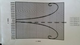
Here is one attempt at using the JMLC horn calculator. I like to avoid room absorbing fiberglass type traps and like the JMLC calculator. The room would be really large on some of the attempts I tried. I tried different flares with 31 to 37 feet throat width. Some of the widths were up to 600 feet wide. The dimensions are in mm.
Here is one attempt at using the JMLC horn calculator. I like to avoid room absorbing fiberglass type traps and like the JMLC calculator. The room would be really large on some of the attempts I tried. I tried different flares with 31 to 37 feet throat width. Some of the widths were up to 600 feet wide. The dimensions are in mm.
Attachments
Here is one attempt at using the JMLC horn calculator. I like to avoid room absorbing fiberglass type traps and like the JMLC calculator. The room would be really large on some of the attempts I tried. I tried different flares with 31 to 37 feet throat width. Some of the widths were up to 600 feet wide. The dimensions are in mm.
Presumably for such a large horn and the natural roll off, to keep it flat to 20Hz this is going to be a potential Jericho moment. At least in a cathedral with its robustness, it can take infra sound energy levels. The whole medical impact of a large horn if driven by a powerful driver should be reviewed but presumably you have done so already.
I find the LeCleach responds best to a good width. Not easy to describe in few words but the horn seems to work to the sides and they represent effective length in what it gives, compared to other horns that seem to need actual physical length.
The amount of roundover seems more important than the cut-off or actual length. For a given mouth space in the room (I'm thinking a lower mid horn in this case) I'd suggest you try a higher cut-off that lets you take the mouth back to at least 135 degrees (for example). Directivity seems less variable. Group delay will have a significant bearing on where you cross it.
The amount of roundover seems more important than the cut-off or actual length. For a given mouth space in the room (I'm thinking a lower mid horn in this case) I'd suggest you try a higher cut-off that lets you take the mouth back to at least 135 degrees (for example). Directivity seems less variable. Group delay will have a significant bearing on where you cross it.
Last edited:
You don't need to hunt for it.AndrewT,
I don't have the time to hunt for the link, ...............
I did and found it in post11 of the Thread you referred me to.
Now that I know what stand means I can confirm that 99% of all known speakers are of the stand type.
How stupid can we get inventing new names for standard shaped speaker boxes.
Just fyi, I have never had a system where aligning the voice coils resulted in time alignment. The phase shifts due to the acoustic slopes of the crossovers always required some offset, typically ~1/4 wavelength at crossover with the LF device closer to the listener. The only way to really know the alignment required for your particular system is to measure the response of the drivers and horns with a fixed time reference for all the measurements and then simulate the crossover and any additional offset required from the driver/horn positions you used for your measurements.
 Guys I removed a cross post (40 instances across the forum) and the comments it generated. Carry on! 😀
Looking at the impulse of lots of horns, I find it really confusing to find the right alignment point. Generally the Sub horn alignments probably are not going to be so critical, but still would like to keep them not to far away from an acoustic distance point of view.Just fyi, I have never had a system where aligning the voice coils resulted in time alignment. The phase shifts due to the acoustic slopes of the crossovers always required some offset, typically ~1/4 wavelength at crossover with the LF device closer to the listener. The only way to really know the alignment required for your particular system is to measure the response of the drivers and horns with a fixed time reference for all the measurements and then simulate the crossover and any additional offset required from the driver/horn positions you used for your measurements.
It is easy. You can just move them in and out to the best sound. That is what matters (Einstein used ordinary toilet paper. He did not used curved toilet paper in real time.)Looking at the impulse of lots of horns, I find it really confusing to find the right alignment point. Generally the Sub horn alignments probably are not going to be so critical, but still would like to keep them not to far away from an acoustic distance point of view.
You can check with varied test frequencies using sine waves, a single microphone and oscilloscope. Dual mikes and dual trace even better. Beats the pseudo unneccessary complexity and hassle
But what it sounds like might surprise you.
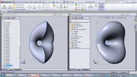
Do we have any information how Jean-Michel calculated elliptical horns? I've tried linearly varying Fc with constant T but it looks much different.
Do we have any information how Jean-Michel calculated elliptical horns? I've tried linearly varying Fc with constant T but it looks much different.
I wish I knew since I want to recalculate a couple of horns for a different throat.
I believe that five different calculations were used and the file was huge. That is why
he did not email me the files.
I have some spreadsheets from him for his elliptical horns from about 6 years ago. I can try to find those and post them.
I managed to produce an stl file for one elliptical horns... A lot of work! what parameters did you have in mind?
- Home
- Loudspeakers
- Multi-Way
- Jean Michel on LeCleac'h horns