Hey
I just wanted to say that my Hirga amplifier its got a lovely sound but im finding compared to the F5 amplifier it is lacking the dynamics and speed and hmmm whats the word, depth at the top end (sounds veiled) , it is a mellow sound maybe a little too valve-like for me it feels like something has made it very mellow.
It does have that Class-A sound so I know its working and biased right and have it biased to spec but Im wondering about changing output transistors on one side or driver transisters.
Hey
I just wanted to say that my Hirga amplifier its got a lovely sound but im finding compared to the F5 amplifier it is lacking the dynamics and speed and hmmm whats the word, depth at the top end (sounds veiled) , it is a mellow sound maybe a little too valve-like for me it feels like something has made it very mellow.
It does have that Class-A sound so I know its working and biased right and have it biased to spec but Im wondering about changing output transistors on one side or driver transisters.
Hi
This Hiraga amplifier is not that easy to properly bias each stage.
If you are interested in a class A topology similar to but at same time different than F5 then maybe add your name on this list for your next build...😉
USSA-5 PCB GB
Fab
Last edited:

Hi! I Have a same problem with my Hiraga with kubota reg. Have you found how to adjust bias? Maybe with R5, R6?Hi again.
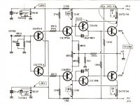
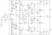
So today I finished both boards from Jim's audio, I hooked one up to 27 volt, and they work nicely, but, bias is a bit low, I measured 200 mili volt across ballast resistors that's roughly 0.6 amps, I would like it to run a bit hotter, 1-1.5 amps, I attach schematics, I hope any of you can help.
Btw offset is pretty good, only slight drift during warm up
Post 352, r5-r6 I put a potentiometer in instead of resistors and adjusted to the wanted bias, let it cook for a while to get stable reading, the desolder the pots and measure what resistor will be needed approximately, be sure to have adequate heatsinking, they do heat up,.
I just checked the pcb, and I used 1k5 in r5-r6, if I remember correct, the intended are 1k8
Last edited:
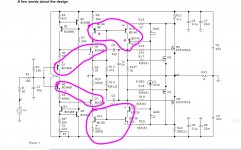
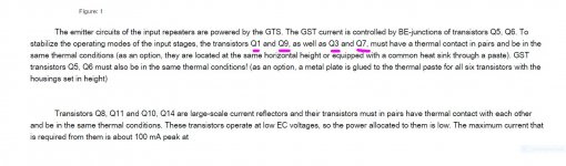
for what I see according to the PDF this transistors with the surround pink circular need to be bound together so that they will share the same temperature?
so is "what I imagine how they go"
Q1 and Q9 they go face each other and united with thermal paste
Q3 and Q7 they go face each other and united with thermal paste
Q8,Q1,Q12 can go on a heat sink
Q10,Q13,Q14 can go on a heat sink
I mean I'm trying to visualize them how they can go oriented on the PCB design
Attachments
You're right, that's also my thoughts, pcb layout is essential to avoid drift, we need prasi, he can draw one up faster than I can finish my coffe
I have a few years doing this but yes you are right he is really fast, I do my projects but take me more time for me I might try it but if Prasi step in I will move away he is too good and I'm saying that in a "good way he is a good man" 🙂
Last edited:
- Home
- Amplifiers
- Solid State
- Jean Hiraga Super Class A 30w Build