Hi everyone,
Well sourcing parts for the JE Labs 300b is a real task for this new guy. Some of the values for the resistors I cannot get, so I ordered as close to as possible. I know not to go under value in wattage rating, but does going higher add more resistance? or more out of my wallet?😉
Oh, I ordered mostly from Angelas and Audio electronics supply.
I got some 99.999 silver wire off eBay for around $2.70 a ft. It's 20awg with teflon shielding included, which I have to install. My question: Will I need thicker awg wire off of the power transformers? or, I should not waste silver on the power side?
Also, still looking for a/c mains inlets and was looking at the IEC computer type ( male) Is this dumb? If not, where can I get some good ones? I can get them for .50 cents. Are these OK? Any Ideas.
Electraprint was working on the trannys, when I called Jack, just to let me know when they are finished, so I can move funds to my account to pay, ( mad money, hidden from WIFE 😀 ). Jack's a real nice guy, surre like talking to him. Said if I let the smoke out of the circuit to give him a call. He also is building the power trans with 7.2 volt taps for the 300b filaments that will be rectified to 5 volts, he's sendind the schematic along. Anyone know what the diagram would look like?
Was thinking of splitting the power supply from the amplifiers, but am not sure what type of connectors to use. The military amphenols are sure to handel the 450 volts, but finding the right ones? was suggested to use octal type, ( old fashioned ) connectors, but I was looking for a more NASA type look.
Finding copper plate is a tough go too. Think 3/16" thick will hold the weight of the trannys and other neat parts? Any ideas where to get small quantities of copper plate?
Base will be made out of wood ( walnut ) I have a ton of it and am real good with woodworking. Dovetail joints and all that. Should I line the wood with something? other than a preservative.😉
Well have to eat and sleep, so once again, to everyone, Thanks a million.
Regards,
Why don't wait till you get the transformer to do your layout and use the leads direct without splicing.
- if you need more wire in the power supply I suggest plain old el cheapo Radio Shack hookup wire-
I've seen several slick looking units with wood bases that used black or painted plexiglass for the top - they looked professional.
It's probably difficult to find copper plate at a reasonable price -
I'm using some 1/8th plate brass that looks good - bought it reasonable but not cheap from a sheet metal shop that keeps some in stock - copper or brass will be high if not a stock item - although you can find sources on the web for single pieces - doesn't seem worth it to me.
One potential easy option - use thick enough plexiglass or aluminum sheet and cover it with thin copper for looks -
My local Lowe's has thin copper sheets reasonably priced. I can't remember the dimensions - not large sheets, but I thought they were large enough for monoblocks. I haven't used them but am thinking about for the next project - they looked thin enough to bend down over the edge and back under a plate of plex.
If you haven't thought of it, you might want to do a rough construction and layout on scrap plywood - get running and debugged - solve any potential layout problems - then build the box for the layout instead of fitting the layout in the box.
High volume sheet metal shop for metal - sign shop for plexiglass if you decide to use it - The last plexiglass I got was from the scrap bin of a sign shop - they gave it to me.
You'll be soldering in no time.
Ken L
🙂
Hi,
I spent months researching looking for parts for the JELabs 300b and during that time stumbled accross Online Metals. Though I did not use them for this projsect, I plan on using them on the next.
Hese is a link to their site:http://www.onlinemetals.com/
As memtioned already, you should be able to build this amp using mostly the component leads of the parts. That is what I am planning on doing anyway.
Best of luck.
ck
btw, I have borrowed a drill press and am now ready to start cutting the holes in my chassis.
maybeim
besides power rating you should remember to watch out for the VOLTAGE rating of the resistors, too.
besides power rating you should remember to watch out for the VOLTAGE rating of the resistors, too.
Higher wattage generally won't hurt, and no, it doesn't add to the resistance. Higher rated resistors often have other advantages, such as a higher working voltage (important for toob amps) and a greater resilience to mishaps during construction or component failure later. The downside is they're usually bigger.maybeim said:Well sourcing parts for the JE Labs 300b is a real task for this new guy. Some of the values for the resistors I cannot get, so I ordered as close to as possible. I know not to go under value in wattage rating, but does going higher add more resistance? or more out of my wallet?😉
Oh, I ordered mostly from Angelas and Audio electronics supply.
I've never used Angela as his handling charges are too great for international orders, but AES are excellent.
Well, I'm anal retentive about everything in my amps, and I wouldn't bother, at least not to start with. Maybe try it later. First up, I'd use Belden PTFE covered cat5. It's cheap, available and has the voltage and temperature ratings, which zip cord might not.I got some 99.999 silver wire off eBay for around $2.70 a ft. It's 20awg with teflon shielding included, which I have to install. My question: Will I need thicker awg wire off of the power transformers? or, I should not waste silver on the power side?
For thicker wire, use multiple strands of the Belden.
Unless you want to get 100% into audiophile nervosa, I'd say an IEC is an IEC is an IEC. The Wattgates <i>might</i> be better but are $50.Also, still looking for a/c mains inlets and was looking at the IEC computer type ( male) Is this dumb? If not, where can I get some good ones? I can get them for .50 cents. Are these OK? Any Ideas.
Some ideas, but I'd be interested in seeing what Jack thinks. Would you post it when you get it please?He also is building the power trans with 7.2 volt taps for the 300b filaments that will be rectified to 5 volts, he's sendind the schematic along. Anyone know what the diagram would look like?
Octals are cheap, work and have the voltage ratings. Put them on the back of the amp where no one can see them. Fancy military locking connectors and the like would be fine, <i>if</i> you can get them cheap enough. However I find it strange to want NASA looking connectors on an amp that will be built in the traditional way of a wood box with everything on the top plate.Was thinking of splitting the power supply from the amplifiers, but am not sure what type of connectors to use. The military amphenols are sure to handel the 450 volts, but finding the right ones? was suggested to use octal type, ( old fashioned ) connectors, but I was looking for a more NASA type look.
I much prefer to have my PSUs on a different chassis.
Not neccessary, but thin copper sheet you can get in hobbyist stores (0.5 - 1mm) would do. I don't bother myself.Should I line the wood with something? other than a preservative.😉
Cheers
Hello,
Ken L.
Thanks Ken, good idea. This did not occur to me. What do you say the minimum thickness should be, of say aluminium? Combined weight of opt and power trannys say, 20lbs total.
I would like them to be able to be detachable, for portability.
Another great idea! Thanks.
Ciscokid,
Thank you for the link. I see this is not inexpensive, copper that is.
I will need to get all the top parts to do a layout, and then I will know what size and price this might cost. So far 10"x14" .250 thick is about $75.00 a piece. Wow!
Good luck with the drill press and post a pic? I'll try to do the same as the project comes along.
grataku,
Voltage ratings, in as? 1k 2w. I assume that there is a way to math magically figure the voltage rating with ohms and watts? I am new. Forgive me and thank you. I am trying to hold to the schematic values when buying parts.
Brett,
I do not think bigger will be a problem, but I have not solder anything yet and I guess as I get into making the hook-ups the space becomes like real estate selling quickly. I have solder a few parts together in my time, but this will be a lot different. I did put out a few dollars for a soldering station, 40watt Weller. Had to send it to the factory where it was built, as soon as I got it home, it did not heat up. Was an *open box buy*. MAN! I was bummed.
I do not want to use the silver on the power cords; I feel this is a waste. I do want to use it in the signal path. There might be some *snake oil magic * going on with the silver wire thing, but I who really knows. I guess it's just cool to say, " silver wire in them amplifiers "
What about XLR type connectors? Can they handle 600-volt surges, just to be on the safe side? What should a wire/connector be rated at for safety margins? If running 450v for b+ should the value be twice at 900v? I would like something nice looking, but not so much the military looking connectors.
As soon as Jack comes through, I'll email him to make sure it's ok to post the filament supply drawing. Copyright crap and all that, I am sure he got the idea from somewhere else.
And as far as IEC connectors, Thank you. I am getting anal over this.😀
Regards all,
Ken L.
One potential easy option - use thick enough Plexiglas or aluminium sheet and cover it with thin copper for looks -
Thanks Ken, good idea. This did not occur to me. What do you say the minimum thickness should be, of say aluminium? Combined weight of opt and power trannys say, 20lbs total.
Why don't wait till you get the transformer to do your layout and use the leads direct without splicing.
I would like them to be able to be detachable, for portability.
If you haven't thought of it, you might want to do a rough construction and layout on scrap plywood - get running and debugged - solve any potential layout problems - then build the box for the layout instead of fitting the layout in the box.
Another great idea! Thanks.
Ciscokid,
I spent months researching looking for parts for the JELabs 300b and during that time stumbled across Online Metals. Though I did not use them for this project, I plan on using them on the next.
Thank you for the link. I see this is not inexpensive, copper that is.
I will need to get all the top parts to do a layout, and then I will know what size and price this might cost. So far 10"x14" .250 thick is about $75.00 a piece. Wow!
Good luck with the drill press and post a pic? I'll try to do the same as the project comes along.
grataku,
Voltage ratings, in as? 1k 2w. I assume that there is a way to math magically figure the voltage rating with ohms and watts? I am new. Forgive me and thank you. I am trying to hold to the schematic values when buying parts.
Brett,
Higher wattage generally won't hurt, and no, it doesn't add to the resistance. Higher rated resistors often have other advantages, such as a higher working voltage (important for toob amps) and a greater resilience to mishaps during construction or component failure later. The downside is they're usually bigger.
I do not think bigger will be a problem, but I have not solder anything yet and I guess as I get into making the hook-ups the space becomes like real estate selling quickly. I have solder a few parts together in my time, but this will be a lot different. I did put out a few dollars for a soldering station, 40watt Weller. Had to send it to the factory where it was built, as soon as I got it home, it did not heat up. Was an *open box buy*. MAN! I was bummed.
Well, I'm anal retentive about everything in my amps, and I wouldn't bother, at least not to start with. Maybe try it later. First up, I'd use Belden PTFE covered cat5. It's cheap, available and has the voltage and temperature ratings, which zip cord might not.
I do not want to use the silver on the power cords; I feel this is a waste. I do want to use it in the signal path. There might be some *snake oil magic * going on with the silver wire thing, but I who really knows. I guess it's just cool to say, " silver wire in them amplifiers "
Octals are cheap, work and have the voltage ratings. Put them on the back of the amp where no one can see them. Fancy military locking connectors and the like would be fine, if you can get them cheap enough. However I find it strange to want NASA looking connectors on an amp that will be built in the traditional way of a wood box with everything on the top plate.
What about XLR type connectors? Can they handle 600-volt surges, just to be on the safe side? What should a wire/connector be rated at for safety margins? If running 450v for b+ should the value be twice at 900v? I would like something nice looking, but not so much the military looking connectors.
As soon as Jack comes through, I'll email him to make sure it's ok to post the filament supply drawing. Copyright crap and all that, I am sure he got the idea from somewhere else.
And as far as IEC connectors, Thank you. I am getting anal over this.😀
Regards all,
1/8 inch aluminum plate
ought to do it - should be cheap and easy to find.
If the sheet metal shop will bend it at 90 degrees on two ends without charge or minimal charge, that will add rigidity and give you something to wrap the copper back around, and gives you additional mounting surface
Hint: don't do this over the phone
if you figure out pretty much what you want, and pick your time ( not Monday or Friday or right before lunch or quitting time) walk in and ask if they can make it out scrap and say you'll pay cash and would like to avoid a minimum billing charge for your hobby project - you stand a good chance of getting it pretty cheap
Time is money and some of these shops can be very, very busy - something like this _can_ be a losing proposition for the shop on a pure commercial business.
However, if you know what you want and don't talk them to death, all they really have to do is pick up a piece make several cuts and bends. And you can be in and out in 10 minutes.
Don't be picky about 1/8th of an inch off of your dimensions, etc. Make the wooden bases to fit _after_ you get the metal.
Then after you do your final assembly - take it everything apart and wrap the aluminum in copper.
HTH
Ken L
🙂
Good advice Ken.
<b>Then after you do your final assembly - take it everything apart and wrap the aluminum in copper.</b>
Al and Cu being dissimilar metals will suffer an electrolytic reaction won't they? Perhaps as a final preparation step before wrapping it in copper, would be giving the Al a fairly liberal coat of some sort of insulation like epoxy. Then wrap, polish the copper and clearcoat it to keep it shiny. Also leave a small length of copper inside the box, and solder an earth lead to it, connected to ground. With it clearcoated it should be insulated, but still a worthwhile safety feature.
Cheers
Brett as usual is correct!
electroysis and corrosion will occur when copper and aluminum are in direct contact for a period of time.
coating as suggested by Brett or possibly a barrier of say plastic- maybe a sheet of gasket material or whatever you may have on hand that you don't have to go out and purchase
Anything that'll make a good barrier between the two and be more or less inert - and be able to take the heat generated -
Thanks for adding that comment, Brett -
I'm not always hitting on all cylinders🙂
Ken L.
Hi,
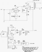
Well here is a schematic of the 7v 1.5a filament supply for a 300b.
Borrowed it off the web. It is a Electraprint design.
I have two Simpson analog meters, 0-100 microamps dc, that I would like to use in my design. Any suggestions as to how to hook them up so I can use them? Would like to use them to bias the amps.
Any way here is the pic:
Attachments
- Status
- Not open for further replies.
- Home
- Amplifiers
- Tubes / Valves
- Je labs 300b round 1 : Ding! Ding!