Last weekend was the European Triode Festival. There's some reports from the (all tube) events here:
http://www.diyaudio.com/forums/clubs-events/178064-european-triode-festival-2010-a.html
JC Morisson, currently a designer for Silbatone in Korea, had a presentation with several unusual but creative tube circuits. Another ETF attendant put these on-line here:
(new adventures in) ultra‐fi: new stuff from jc morrison
Enjoy!
jan didden
Hi Jan;
Do you mean CCS loaded pentode? How well it drives grid currents and Miller capacitances?
Do you mean CCS loaded pentode? How well it drives grid currents and Miller capacitances?
Hi Jan;
Do you mean CCS loaded pentode? How well it drives grid currents and Miller capacitances?
Hi Anatolyi,
I have no expreience with these circuits, but they look different and innovative so that's why I posted the link here.
Apparently they are used in the no-holds-barred Silbatone equipment.
JC specifically said he wanted them out in the open to avoid some 'smart' guys to patent them.
jan didden
Hi Anatolyi,
I have no expreience with these circuits, but they look different and innovative so that's why I posted the link here.
Apparently they are used in the no-holds-barred Silbatone equipment.
JC specifically said he wanted them out in the open to avoid some 'smart' guys to patent them.
Smart decision; I often do the same! 😉
I am going to publish Vostok solid state assisted tube amp soon...
I'm still breadboarding it, to explore all possibilities.
It is kind of new replacement for SRPP, with some better qualities.
Nice to see someone out there being creative for a change. Now, if you combined that pentode circuit with Frank Bloehbaum's hybrid screen setup...
Even if the the circuit is DC-connected from input to output, it still must be AC-connected signal-wise as C1 shorts the CCS.
About innovative circuits at ETF, Frank (Blohbaums?) Gm-circuit really should be mentioned. Used in his presented phono-amp.
About innovative circuits at ETF, Frank (Blohbaums?) Gm-circuit really should be mentioned. Used in his presented phono-amp.
Last edited:
Nice to see someone out there being creative for a change. Now, if you combined that pentode circuit with Frank Bloehbaum's hybrid screen setup...
I understand the two are talking a lot.... (to each other).
jan didden
I'm not quite sure what the point of these inverted circuits is. Have I missed something?
If your first stage has a very high output impedance you had better be sure that your second stage has a very linear input impedance and very low Miller capacitance. Also very low heater-cathode leakage in the first valve, even with a DC heater, as this appears in parallel with the output unless you bootstrap the heater supply reference voltage. There is a reason why, until recently, most people used the classic simple circuits - and it was not ignorance!
If your first stage has a very high output impedance you had better be sure that your second stage has a very linear input impedance and very low Miller capacitance. Also very low heater-cathode leakage in the first valve, even with a DC heater, as this appears in parallel with the output unless you bootstrap the heater supply reference voltage. There is a reason why, until recently, most people used the classic simple circuits - and it was not ignorance!
Gary Pimm shows some work on CCS loaded pentodes, and I have recently seen a power amp schematic somewhere showing exactly the same concept. So Mr Morisson himself, or anybody else willing to burn up some money, could probably still apply for a USPTO patent, maybe even get it, but it would never survive a trial process if someone was willing to challenge it (I don't know the exact terms in English).
Mmmh . . .
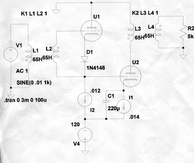
Ground the negative terminal of V4 and tie its positive terminal to the anode of U1 without grounding it of course.
In short, move the ground from V4+ to V4-
Does this deserve a patent ?
What do I miss ?
Yves.
Ground the negative terminal of V4 and tie its positive terminal to the anode of U1 without grounding it of course.
In short, move the ground from V4+ to V4-
Does this deserve a patent ?
What do I miss ?
Yves.
Mmmh . . .
Ground the negative terminal of V4 and tie its positive terminal to the anode of U1 without grounding it of course.
In short, move the ground from V4+ to V4-
Does this deserve a patent ?
What do I miss ?
It reminds me spam can transformers and light bulb load, with GM-70 tubes... 😉
Mmmh . . .
Ground the negative terminal of V4 and tie its positive terminal to the anode of U1 without grounding it of course.
In short, move the ground from V4+ to V4-
Does this deserve a patent ?
What do I miss ?
Yves.
Don't think it would make a difference. JCM would probably like it; he made it clear that there's no reason to talk abour 'B+' as sacred; 'B-' is just as good.
BTW His stated purpose in publishing this is to make sure there's NO chance anyone could patent it.
So, don't spoil it ...😉
jan didden
JC Morrison would be an interesting interview for you to do. Did you do one, yet? Great guy, great stories, lots of intuition and design experience.
The interwinding capacitance of L1 and L2 is going to put a serious damper on the slew rate of two high Z CCS's driving a grid (pentode version, well if it really were a pentode version, see below).
----------
"Now, if you combined that pentode circuit with Frank Bloehbaum's hybrid screen setup..."
The pentode's plate and screen currents are both going to ground. I assume you mean the usual Mosfet follower bypass of screen current to the plate idea that has been around for some time (Source to screen grid, +Vscrn reference voltage on the gate, and drain to plate; then fancier versions for power stages where Vplate drops below Vscrn) . Doesn't seem to do anything for this circuit though?
Guessing that improving the Hi Z property of the pentode current source is the goal, I think the simplest fixup would be to reference the screen grid to the cathode so it acts like a pentode rather than a triode (which it is as configured). A cap/zener from cathode to screen grid, and a LND150 CCS from screen grid to ground (being at + potential here with reference to the cathode).
Last edited:
"I suppose you saw his own weblog: new amp design @ Lab JC"
No schematic comes up when I access that link, although it mentions one. From the verbal description, it is using a signal modulated pentode current source with a CCS load to get very high gain, sort of the flip version of what was posted earlier. The reason one can get good linearity this way is that only a tiny part of the pentode transfer curve is being used, downside is the very high impedance output which can't drive much capacitance or R.
It would be of some interest to know how the CCS load for the pentode is constructed there. If it has similar non-linearity to the driven pentode, then a lower R load can be used (a larger portion of the V to I transfer useable). This would require something like the Aikido input stage, but with two matched pentodes stacked up instead of triodes.
- Status
- Not open for further replies.
- Home
- Amplifiers
- Tubes / Valves
- JC Morrison circuits