.............🙄

image hosting

image hosting
carnt really draw what i mean, cos the sygenery horn has so many angles..
quintessentially its just the sygery horn with a sub each side built in to match the odd angles.... nothing special really
image hosting
image hosting
carnt really draw what i mean, cos the sygenery horn has so many angles..
quintessentially its just the sygery horn with a sub each side built in to match the odd angles.... nothing special really
Last edited:
Your prior pictures of pointing multiple full range horns in to a larger horn would cause terrible interference patterns, exactly what the Synergy horn concept is designed to eliminate..............:
carnt really draw what i mean, cos the sygenery horn has so many angles..
quintessentially its just the sygery horn with a sub each side built in to match the odd angles.... nothing special really
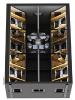
There are many different ways to fold bass horns, but the way it is done in the JH-90 works quite well already 😉.
The picture below shows the JH-90 with the bass horn front panels removed.
Art
Attachments
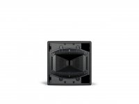
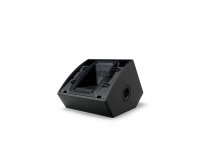
Now Bose is getting in on this.
This is the new Bose AMM series.
This is the new Bose AMM series.
Attachments


i dunno what to think guys; every synergy i've built/measured, has shown a surprisingly shorter time of flight from the CD, than from the drivers mounted on the horn walls. This is without any filters messing up timing.
As the CD is further away physically (from measurement mic), i'm like 'go figure'.
The best i've come to is apparent and measured acoustic centers differ from geometric centers/distances. Any illumination appreciated.
As the CD is further away physically (from measurement mic), i'm like 'go figure'.
The best i've come to is apparent and measured acoustic centers differ from geometric centers/distances. Any illumination appreciated.
The electrical and acoustical filters on the midranges delay the signal.
For instance, if the mids are rolling off at 1350Hz with a second order slope, due to the acoustic filter, and they're also rolling off with a 2nd order electrical filter, you'll see a full wavelength delay at 1350Hz (ten inches.)
Something I've noticed with a lot of the DIY Unity horns is that they try to get the mids as close to the tweeter as possible. That's not ideal, because the midrange low pass filter, both acoustic and electric, introduces a significant delay.
i dunno what to think guys; every synergy i've built/measured, has shown a surprisingly shorter time of flight from the CD, than from the drivers mounted on the horn walls. This is without any filters messing up timing.
As the CD is further away physically (from measurement mic), i'm like 'go figure'.
The best i've come to is apparent and measured acoustic centers differ from geometric centers/distances. Any illumination appreciated.
The midrange port is indeed closer to the mic than the CD's exit but the midrange's voice coil and acoustic center are well behind the horn wall so could well have a longer physical path. Plus as Patrick says you will get some group delay from the bandpass chamber even with electrical filters off.
Hi guys, yeah, all both of you are saying makes sense.
Patrick, i feel confident the relative delay of the mids is not due to electrical delay.
The relative delay to the CD is there when no filters are in place (raw measurements).
And it's there when I use linear phase filters which add a constant delay no matter the chosen low pass frequency.
So it makes me think it's the mids' acoustic lowpass delay.
Jack, even after I account for the longer physical path to the mids voice coil, the CD is still farther away. Again making me think it's acoustic delay.
First chance i get, i'm going to compare measured time-of-flight to the CD, to the physical mic distance as precisely as possible. If the distances equate, i think that means the relative time anomaly simply has to be from the mid's acoustic low pass.
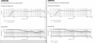
1) Both the Bose AMM108 &112 use passive crossovers and achieve reasonably flat frequency response. The combination of electrical and acoustical filters used to achieve that is unknown without looking at the crossover schematic.1)The electrical and acoustical filters on the midranges delay the signal.
For instance, if the mids are rolling off at 1350Hz with a second order slope, due to the acoustic filter, and they're also rolling off with a 2nd order electrical filter, you'll see a full wavelength delay at 1350Hz (ten inches.)
2)Something I've noticed with a lot of the DIY Unity horns is that they try to get the mids as close to the tweeter as possible. That's not ideal, because the midrange low pass filter, both acoustic and electric, introduces a significant delay.
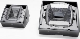
2) Notice that the SynTripP raw combined response of the 2x10" LF placed as near as physically possible to the HF driver results in smooth phase response through the overlap region-both LF and HF arrival time are nearly the same.
The Bose AMM108 & AMM112 beamwidth does not conform well to the nominal 110 Horizontal x 60 Vertical pattern, the AMM108 "beaming" to 65 degrees H at 5kHz (40 V), then widening out again. The AMM112 holds pattern a little lower, but "beams" in to 70 degrees H at 4kHz (30 V), then widens out again.
With many other co-ax monitors already offering smoother (and more useful) beamwidth without resorting to a perforated diffraction horn, the Bose entry is not likely to convert any buyers not already on their bandwagon.
At least their stated output levels look believable !
Art
Attachments
Last edited:
First chance i get, i'm going to compare measured time-of-flight to the CD, to the physical mic distance as precisely as possible. If the distances equate, i think that means the relative time anomaly simply has to be from the mid's acoustic low pass.
That is what Sherlock Holmes would say. When you've eliminate all other possibilities whatever remains, however unlikely, must be "it".
Here are a couple of Synergy bandpass group delay simulations, for the 4" driver I actually used and for a 15" that never went any further.
Attachments
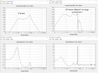
Hmmmm. Thought here.... In terms of phase response, a filter's order determines the rotation or group delay present, ergo the second order filter due to the bandpass chamber cannot be changed and thus the overall group delay cannot be changed, but correct me if I'm wrong, the q of the filter can be....?
Aperiodic chambers are designed to flatten the acoustic q of a system by introducing a resistive load instead of a reactive one. If the chamber in front of a driver was loaded with a resistive medium would the q of the filter not be flattened, thus increasing the bandwidth of phase rotation.
The reason I ask this is in regards to PB's comments earlier in the thread discussing group delay spikes at the acoustic filter locations. In my mind the smoothest (thus lowest q) filtering possible would produce the flattest phase response, which would be beneficial in both matching of driver's phase and overall system phase response.
Please feel free to point out any inconsistencies or mistakes in my logic, I've come a long way in understanding synergy horns but there's still far more to learn.
That is what Sherlock Holmes would say. When you've eliminate all other possibilities whatever remains, however unlikely, must be "it".
Here are a couple of Synergy bandpass group delay simulations, for the 4" driver I actually used and for a 15" that never went any further.
Good ole Sherlock...his straightforward logic has bailed me out more than once 😀
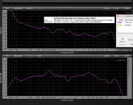
Had a chance to carefully measure physical distance vs measured distance, on a new synergy prototype .
Here's a spreadsheet snip that i hope reads clear.

Along with the measurement of an electrical filter designed to match the acoustic rolloff of the 10 mid cones raw response.
The delay finder's "Current Delay Setting" of 3.17ms is the processor's fixed latency with no filters in place.
So the Delta Delay of 0.79ft or 0.70 ms is the delay of a BW4 @640Hz.

Which ties together physical distance and measured timesnicely, and makes me say case closed.
The culprit be the acoustic rolloff of the low passed section ....the one we all suspected. 😀
Mark/Sherlock,Had a chance to carefully measure physical distance vs measured distance, on a new synergy prototype .
Along with the measurement of an electrical filter designed to match the acoustic rolloff of the 10 mid cones raw response.
The delay finder's "Current Delay Setting" of 3.17ms is the processor's fixed latency with no filters in place.
So the Delta Delay of 0.79ft or 0.70 ms is the delay of a BW4 @640Hz.
Which ties together physical distance and measured times nicely, and makes me say case closed.
The culprit be the acoustic rolloff of the low passed section ....the one we all suspected. 😀
Not sure what culprit you be chasing

Your delay finder measured distance between the 10" LF cones and the HF driver is only 3", about 52 degree phase difference at 640Hz. As that length/time is well under 1/4 wavelength (90 degrees) difference, the LF and HF driver's raw response would acoustically sum together with no electrical filters or delay required.
A 24dB per octave filter is "four pole", each pole adding 90 degrees of phase rotation, a total of 360 degrees, equal to one complete cycle of a frequency.
The time period of 640Hz in ms is 1000/640=1.5625ms.
The blue line on your magnitude graph appears to have both a HP and LP filter applied, not sure what the Delta Delay of 0.79ft or 0.70 ms actually represents, though not sure if you want to re-open that case 😉
Watson
Mark/Sherlock,
Not sure what culprit you be chasing
Your delay finder measured distance between the 10" LF cones and the HF driver is only 3", about 52 degree phase difference at 640Hz. As that length/time is well under 1/4 wavelength (90 degrees) difference, the LF and HF driver's raw response would acoustically sum together with no electrical filters or delay required.
A 24dB per octave filter is "four pole", each pole adding 90 degrees of phase rotation, a total of 360 degrees, equal to one complete cycle of a frequency.
The time period of 640Hz in ms is 1000/640=1.5625ms.
The blue line on your magnitude graph appears to have both a HP and LP filter applied, not sure what the Delta Delay of 0.79ft or 0.70 ms actually represents, though not sure if you want to re-open that case 😉
Watson
Hi Watson/Art,
We caught the culprit with the missing 0.7ms mid-cone delay in his pocket, that he stole from the processor.
To evidence the case; Red is without the delay in place, vs Green with.
Actual xover is at 500Hz. (as seen)

The 640Hz number came from the frequency of the electrical lowpass filter, a BW4, that matched the raw acoustic lowpass of the mid drivers. Put that BW4 @ 640 lpf filter in any of our measurement programs, and get about 0.7ms delay.
Seems to me, the electrical filter's delay that matches the raw acoustical rolloff, tells us the difference in a drivers physical acoustical center and its apparent acoustical center.
IOW, where the voice coil is, vs where measuring says peak energy comes from.
In the case on the 10" mids here, note the difference in the spreadsheet of 9.4"...or 0.69ms. Same delay of the BW$ filter that matches the raw LP acoustic rolloff.
(So the simple approx 3" measured distance difference between mid and CD is not the relevant timing measurement.)
I think anytime there has been delay introduced from raw acoustic low pass, it has to be added to physical-center distance delay. It appears electrical filter matching can tell us close to precisely, how much.
Oh, the blue line mag trace you mentioned, that appears to have both a HP and LP, does. I'm using QSC CX amps, all with their 33Hz hpf on. So doesn't matter measurement wise.
On to the next case i hope ! 😉
Hmmmm. Thought here.... In terms of phase response, a filter's order determines the rotation or group delay present, ergo the second order filter due to the bandpass chamber cannot be changed and thus the overall group delay cannot be changed, but correct me if I'm wrong, the q of the filter can be....?
Aperiodic chambers are designed to flatten the acoustic q of a system by introducing a resistive load instead of a reactive one. If the chamber in front of a driver was loaded with a resistive medium would the q of the filter not be flattened, thus increasing the bandwidth of phase rotation.
The reason I ask this is in regards to PB's comments earlier in the thread discussing group delay spikes at the acoustic filter locations. In my mind the smoothest (thus lowest q) filtering possible would produce the flattest phase response, which would be beneficial in both matching of driver's phase and overall system phase response.
Please feel free to point out any inconsistencies or mistakes in my logic, I've come a long way in understanding synergy horns but there's still far more to learn.
All makes good sense to me. 🙂
(Other than the resistive, reactive part, which I'm only just beginning to learn about)
To me, Low Q peaking or rolloffs acoustically, low order/Q IIR electrically, simply makes for flatter phase, .......which be very, very, good !
Mark,The 640Hz number came from the frequency of the electrical lowpass filter, a BW4, that matched the raw acoustic lowpass of the mid drivers. Put that BW4 @ 640 lpf filter in any of our measurement programs, and get about 0.7ms delay.
Seems to me, the electrical filter's delay that matches the raw acoustical rolloff, tells us the difference in a drivers physical acoustical center and its apparent acoustical center.
(So the simple approx 3" measured distance difference between mid and CD is not the relevant timing measurement.)
I think anytime there has been delay introduced from raw acoustic low pass, it has to be added to physical-center distance delay. It appears electrical filter matching can tell us close to precisely, how much.
Curious as to what delay time you measure through the electrical highpass that most closely matches the raw acoustical rolloff of the HF?
Art
Sure thing. Which section of the dcx464 did you mean; the lower one HF, or the upper one VHF?
(i use the term HF to distinguish the CD section from synergy cone mids)
Whichever, my takes are:
That the electrical highpass that matches the HF section is close to a 500Hz BW2.
And the hpf that matches VHF is close to a 3.2kHz BW4.
Neither one of course, will impose any electrical delay, being highpass only.
Bringing in a lowpass of the HF section adds 0.12ms delay, using a 5.6kHz BW7 electrical that matches the acoustical lowpass.
(No low pass required for VHF section.)
Here's HF raw, along with electrical 500 BW2, and 3.2k BW7.
(note delay finder 3.29, and recall processor has 3.17ms fixed latency)
Mark,
My apologies as to the ambiguities of my question, but thanks for your answer including measured delay of the LP filter equivalent to acoustical lowpass of the low portion of the coax DCX464 compression driver.
Frequency and wavelength time period in ms (milliseconds, 1/1000 of a second) have a fixed, linear relationship:
1000/50Hz=20ms, 1000/500Hz=2ms, 1000/5000Hz=0.2ms, etc.
Each “pole” of an IIR (Infinite Impulse Response) filter imparts a 6dB per octave change in frequency response and a 90 degree phase shift from low to high frequency.
Half the total phase shift is reached at the crossover frequency, you measured the 640Hz BW4 delay at 0.70 ms, close to half the time period of 640Hz (1.5625ms).
The low portion of the coax DCX464 compression driver was equivalent to a 5.6kHz BW7 (1000/5600=1.78ms).
90x7=630 degrees of phase shift =1.75 wavelengths x 1.78ms =0.3115ms.
0.3115/2=0.156ms, also close to the 0.12ms delay you measured.
Close enough for rock & roll, and Watson 😉
- Home
- Loudspeakers
- Multi-Way
- JBL's take on the Unity Horn