After poking thru the schematic, I think you are talking about the 4 silver diodes.
D301=1.44v
D331=11.97v
D231=11.77v
D201=11.88v
Audio is quite distorted now. 🙁
Scope says only half of the wave is being produced. n_n_n_n
paul
D301=1.44v
D331=11.97v
D231=11.77v
D201=11.88v
Audio is quite distorted now. 🙁
Scope says only half of the wave is being produced. n_n_n_n
paul
D301 is leaky. It determines the drive voltage for the 1 bank of outputs. If the voltage isn't sufficient the outputs can't be driven on (efficiently).
This is the original:
512-1N5242B
Many Thanks!
These new ones look different..
Should I replace all 4 or just the one?
Ok back running a speaker.
1 side of outputs gets hotter than other during operation.
Do I have poorly matched outputs?
I bought them from Tayada IRF, a few were bad straight away, the ones I installed were within 300Mohms of each other.
Thanks!
paul
1 side of outputs gets hotter than other during operation.
Do I have poorly matched outputs?
I bought them from Tayada IRF, a few were bad straight away, the ones I installed were within 300Mohms of each other.
Thanks!
paul
Confirm that you have a good square wave on the gate legs of EACH output FET. It should have an amplitude of ~10v. Compare the cool side to the hot side.
Hi
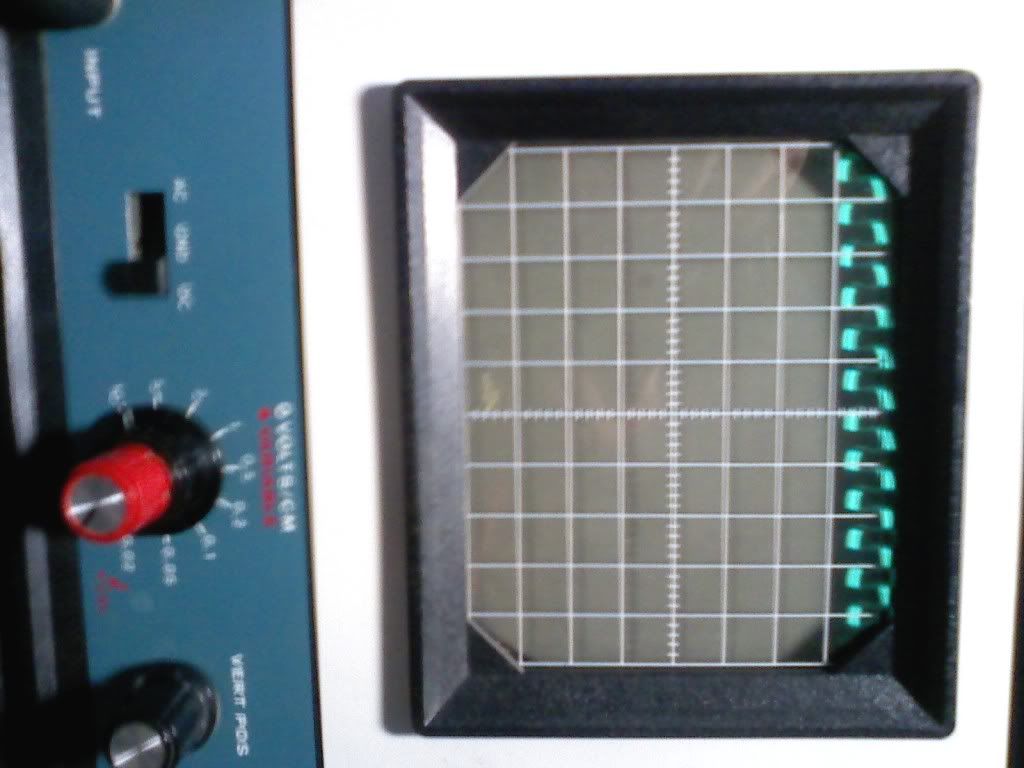
Pics of scope one side of amp then other:
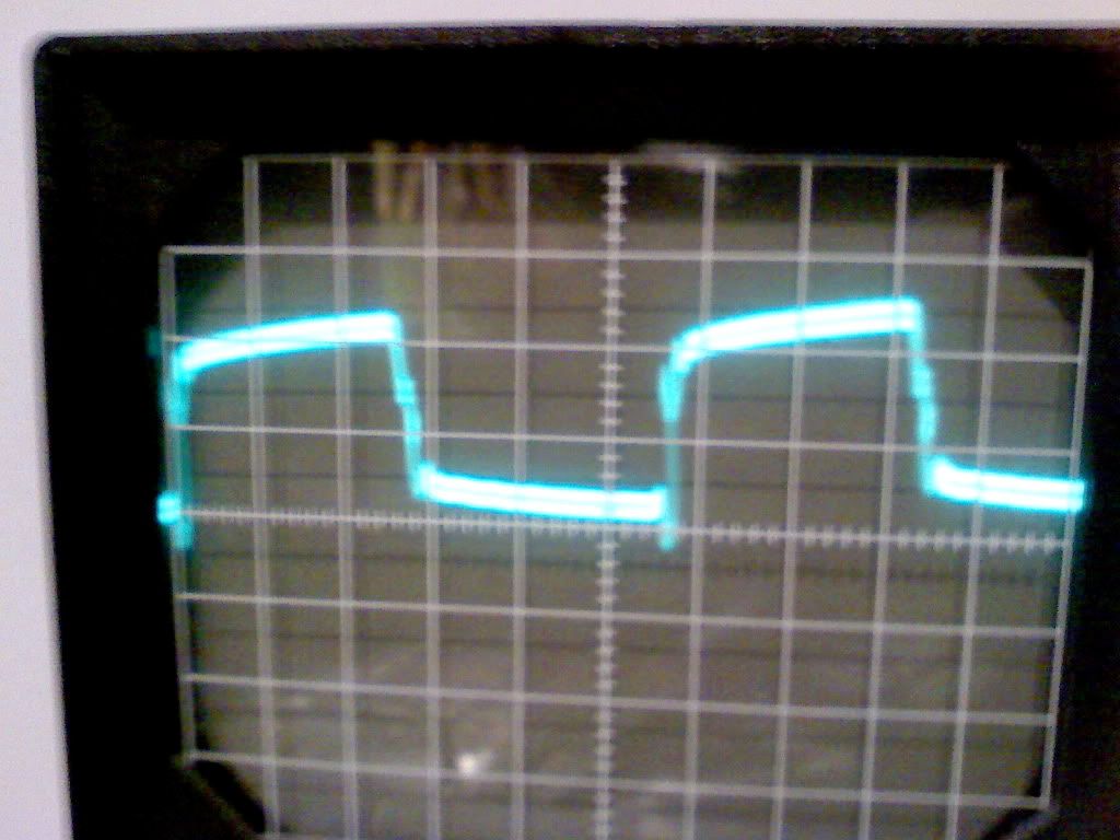
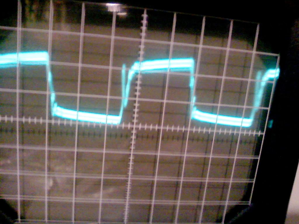
Scope does not show amplitude voltage, cooler side is 35.5V
hotter side is 36.4V Taken at idle no sound input.
paul
Pics of scope one side of amp then other:
Scope does not show amplitude voltage, cooler side is 35.5V
hotter side is 36.4V Taken at idle no sound input.
paul
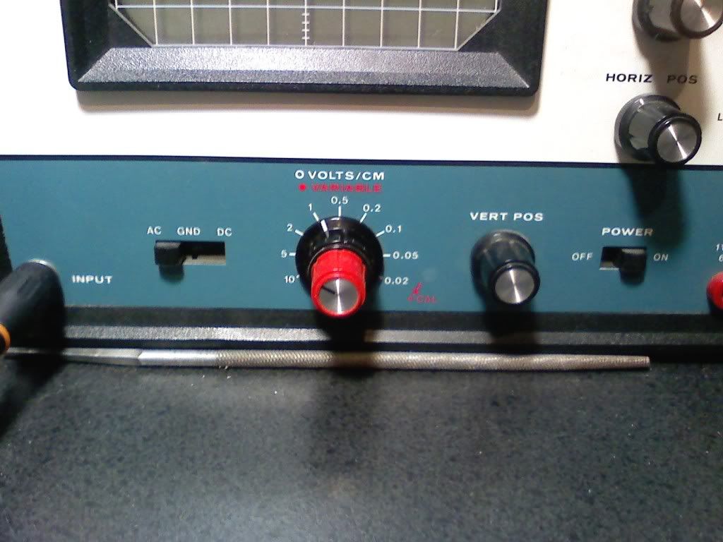
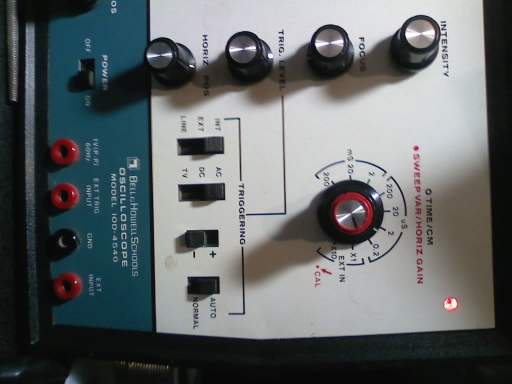
Here are pics of the scope, it was free....
Where is a good place to get the IRF's for this?
I don't want to wait 3 weeks again for 1/4 of an order of useless parts..
I smoked all the outputs again
🙄
Where is a good place to get the IRF's for this?
I don't want to wait 3 weeks again for 1/4 of an order of useless parts..
I smoked all the outputs again
🙄
Last edited:
Octopart - Electronic Parts, Electronic Components, Datasheets
You can use this search engine to find electronic components.
The red knob needs to be in the fully clockwise position. Check the calibration of the scope (roughly) by positioning the trace precisely on the reference line, setting the vertical amplifier to 5v/div and touching the probe to your 12v power supply. It should deflect upwards ~2.5 divisions.
You should also calibrate the probe. There should be a cal test point somewhere in the scope (banana jack marked 1v p-p?). Set the probe so that the tops and bottoms of the calibration waveform are perfectly flat.
Thanks for the link.
Red knob, the 'variable' or 'sweep'?
I am getting more sensible displays now that they are both all the way clockwise.
12V sends it about where you suggest.
I have amp idling again.
Red knob, the 'variable' or 'sweep'?
I am getting more sensible displays now that they are both all the way clockwise.
12V sends it about where you suggest.
I have amp idling again.
Both variable knobs should remain fully clockwise. That's the only way the markings on the controls will be accurate.
Are you seeing ~10v of amplitude on the gates of all of the FETs?
Are you seeing ~10v of amplitude on the gates of all of the FETs?
Set the scope the same as in the photo. You should have a drive signal very close to what's shown in the photo (it's DC coupled). If the amplitude is significantly less, we'll have to try to determine why.
After you set the scope, touch it to the B+ terminal to see if it deflects just over 1/2 division.
After you set the scope, touch it to the B+ terminal to see if it deflects just over 1/2 division.
Attachments
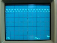
If this is set to 20v/div, it looks about right but I think your scope needs to be adjusted. That's far more than 3v.
Did you calibrate the probe?
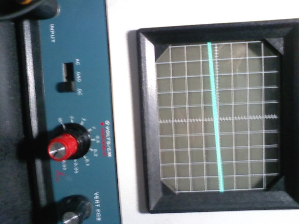
You need to find the astigmatism and focus controls. Adjust them (alternately) until you get a clean, sharp trace.
Also find the trace rotation pot. it will straighten the trace. If the trace is straight when the scope is in other locations, you may have a strong magnet near the scope that's pulling it off.
Did you calibrate the probe?
You need to find the astigmatism and focus controls. Adjust them (alternately) until you get a clean, sharp trace.
Also find the trace rotation pot. it will straighten the trace. If the trace is straight when the scope is in other locations, you may have a strong magnet near the scope that's pulling it off.
- Home
- General Interest
- Car Audio
- JBL BP 1200.1 Project