Hi all,
Just thought I would let you know that I've put my web page back up. I'll be adding some new stuff as time permits. The first new thing that should be up in a couple of days is a differential transconductance amplifier built using the self bias CCS's as building blocks. I developed it during the same time frame that John Swenson was developing his SE transconductance amps.
I'll also present a way to use one of the CCS's as a test tool to measure power supply performance.
On to CCS measurements. All the CCS measurements in the performance section were taken with the CCS's running 6.5ma @ 150V. The first measurements made were for line stages and I just continued at the same operating point for comparison reasons. In other testing and use I've run the CCS's as high as 400ma.
Later this winter I want to work on a new way of measuring the performance of CCS's. The old way was done by making a bunch of single frequency measurements and recording the results in Excel. I have upgraded my measurement hardware from the old sound blaster card that had SE outputs and inputs to a M-Audio audiophile 192K with balanced inputs and outputs. Also developed a input buffer that provides signal conditioning and input protection for the sound card. I'm hoping to be able to do semi-automated measurements that span 5Hz to 95Khz with direct display of the results.
Gary
Hi Gary
First, many thanks for putting the web page online again. And the additions sound vey interesting! After reading Nelson Pass's paper on transconductance power amplifiers and fullrange drivers I have spent some time on the theme (John Swenson's transconductance power amp, blogs by Broskie), and would like to experiment it too, someday, so all information is most welcome.
Erik
beamnet said:I have the IXYS now. I'm reading all tis stuff.
Can anyone point me to a (cascoded) ixys used as a current sink in a HV application (110V)?
Thanks a bunch
Here is a thread with some discussion and an example of cascoded Ixys chips. Seems cascoded chips and high current don't go together.
http://www.diyaudio.com/forums/showthread.php?postid=962019#post962019
Good luck, Erik
Thanks eric. Now i see that a cascoded ixys can be wired as a 2 connection device and can work as a sink. I'll definitely go for that.
I am running 8ma/tube, so 16 mA total. So the ixys will handle that perfectly.
If i would want to experiment with a cascoded penthode, like tubelab does, but have no room for a giant sweep tube, would anybody know of a handy small penthode that would have a low voltage drop?
Ill measure some myself...
Bas
For those looking, http://www.mouser.com now carries the IXYS 10M45. They are more expensive than Digikey, but the difference is probably less than shipping on a separate order of you are ordering from Mouser anyway. Plus, Mouser carries the DN2540 so it is one stop shopping if you feel compelled to compare them.
luvdunhill said:dsavitsk:
where should we look for your new PCBs? I hope you go through with the GB!
I sent an email to a mod and am waiting for an okay.
http://www.mouser.com now carries the IXYS 10M45.
Mouser had a few of the 900 volt 10M90 in stock. They would help me in my quest for a driver capable of 500 volts P-P output, so I couldn't resist and bought them all. They have more on order. I plan to test these guys out thouroughly early next year.
The cascoded tube circuit shown on my web site did indeed use a big sweep pentode, but it was triode wired. Figure out how much current you need, and look for a tube that requires at least 5 volts of bias, but less than 10 volts to get that current at your expected plate voltage.

Does anyone know how to calculate the output impedance of this CCS when used as a plate load and the output is taken from the mu follower (Low Z) output?
Since the Source terminal of the bottom DN2540 looks like HiZ + Rset = HiZ to the bottom load device with no Lo Z output load connected, a pretty good guess would be that the bottom device sees LoZload+Rset when connected.
Don
Don
Resurrecting an old thread, in particular the last two posts.
I'm still not getting the "Lo Z" mu output idea of these cascoded CCS's. When using the standard two terminal CCS model, the load sees a voltage source in series with Rp. When using the mu output terminal, the load sees ???????
Is there a relationship to the actual current of the CCS, or just Rp ?
I'm still not getting the "Lo Z" mu output idea of these cascoded CCS's. When using the standard two terminal CCS model, the load sees a voltage source in series with Rp. When using the mu output terminal, the load sees ???????
Is there a relationship to the actual current of the CCS, or just Rp ?
Resurrecting an old thread, in particular the last two posts.
I'm still not getting the "Lo Z" mu output idea of these cascoded CCS's. When using the standard two terminal CCS model, the load sees a voltage source in series with Rp. When using the mu output terminal, the load sees ???????
When using the mu output, the load sees a voltage source with a "Thevenin equivalent" series resistor approximately equal to 1/gfs of the MOSFET. A closer approximation is (1/(gfs - 1/R)) where R is the source resistor (Rset) which degenerates some of the MOSFET gfs.
Since some small fraction of load current will be seen by the tube, there will be some effect of Rp that may become significant for high-Rp tubes and low Rset values.
Michael
Thanks Michael:
So if I can glean one of the more significant practical aspects of this, it is that the use of the "driver" tube is somewhat independent of the "output" tube. That is, we normally desire to ensure the Rp of the driver tube is selected appropriately for the load (capacitive primarily) of the output tube.
But, when using the mu output, a non-ideal (wimpy) driver tube can be used to drive a heavy load. Like a 12AX7 driving a 300B through the mu output can actually work. Is this a fair assumption?
Thanks Michael:
So if I can glean one of the more significant practical aspects of this, it is that the use of the "driver" tube is somewhat independent of the "output" tube. That is, we normally desire to ensure the Rp of the driver tube is selected appropriately for the load (capacitive primarily) of the output tube.
But, when using the mu output, a non-ideal (wimpy) driver tube can be used to drive a heavy load. Like a 12AX7 driving a 300B through the mu output can actually work. Is this a fair assumption?
I have thought about using a 12AY7 in this arrangement driving a 300B. Gain would be about 44, which is enough input sensitivity for my purposes.
The driver tube still has to drive the Crss of the top MOSFEt in the cascode, which even if one assumes 5pf MOSFET + 5pf wiring and interelectrode is 10pF. I think it's questionable for a 12AX7 to drive this at 160VP-P but it does put it into the realm of possibility. Maybe with both sections in parallel?
10pF is a lot better than the 50pF or more that directly driving the 300B grid would give you, so I think one could get away with a much higher Rp driver than for example with choke loading.
Anyway here is an approximate load line for capacitive load of 10pF on both sections of a 12AY7 with a 40 KHz, 180V P-P sine wave (0.22 mA at 22V/uS) note the different place the load line crosses the -2V grid line in each direction (looks like slight slew-induced distortion).
Attachments
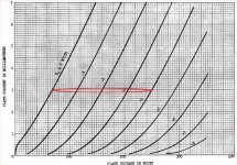
From Gary Pimm
The drawback to this arrangement is the current to drive the next stage comes from the power supply, it violates the design concept of separate paths for AC and DC.
An externally hosted image should be here but it was not working when we last tested it.
Yeah, I read that too, David. Don't know that it really concerns me. The concept of separate AC/DC paths is a good one, but if any stage is most immune to the negative effects, I would think it's the output stage.
I also read on Gary's site that the output impedance of the mu stage was around 500 ohms. By calculation with transconductance I get around 5 ohms. I guess either number is still pretty good for the application.
I also read on Gary's site that the output impedance of the mu stage was around 500 ohms. By calculation with transconductance I get around 5 ohms. I guess either number is still pretty good for the application.
Yeah, I read that too, David. Don't know that it really concerns me. The concept of separate AC/DC paths is a good one, but if any stage is most immune to the negative effects, I would think it's the output stage.
I also read on Gary's site that the output impedance of the mu stage was around 500 ohms. By calculation with transconductance I get around 5 ohms. I guess either number is still pretty good for the application.
I'm at a loss for why this "design concept" is important here. I think the mu output is isolated from power supply noise by the dynamic impedance of the MOSFET.
Also when calculating the Zo based on gfs, be sure to use the gfs at the chosen op point, not the data sheet gfs, usually specified at high current. MOSFET gfs at tube amp currents is on the order of 40 mA/V:
http://www.diyaudio.com/forums/tube...ollowers-low-10ma-currents-2.html#post1939558
Based on this, the Zo should be on the order of 25 ohms, which is far closer to what I observe using a 1N60 or DN2540 than the 500 ohms quoted from Gary's site.
Try it and see.
Michael
I''m guessing that the 500 ohm output impedance referenced is from the CCS assisted pentode driver section. In this situation the tubes were pentodes and the plate resistance of the circuits was high, in the 33K to 47K range.
Measurements made on triode circuits showed much lower output impedance. In my phono preamp where the bias current was only 2.5ma the output impedance was ~450 ohms. The line stage experiments where the current was in the 6ma range the output impedance dropped to the 200 ohm range. At currents in the 15ma to 20ma the output impedance was in the 50 to 75 ohm range.
In the case where you want to use a low current high gain tube to drive an output tube you can use the CCS to set the current for the gain stage and add either a resistor or CCS to ground from the MU output to increase the current in the MOSFETs to get lower output impedance. This was done in the active loaded 300B amp starting with rev 2.
The output impedance of the MU output is proportional to the current flowing in the MOSFETs. Increase the current to decrease the output impedance.
- Status
- Not open for further replies.
- Home
- Amplifiers
- Tubes / Valves
- Ixys IXCP10M45s IC