Fixed link here: [JN] electronics
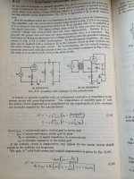
Unfortunately the attachment was scrubbed from the post and Morrison doesn't explain its operation. At first glance it looks like a regular pentode cathode follower with an active cathode load M1/R5 and screen regulation, except:
- the screen looks held at Vpk/2 instead of a constant screen/cathode V
- D1 in the cathode
- the 10k on the transformer secondary
Is the original schematic available? Maybe here?
(new adventures in) ultra‑fi: new stuff from jc morrison
I am still waiting for one to be built just as in the schematic that is in Post # 12 . . .
And then waiting for the test results.
And then waiting for the test results.
It has no plate load and source is applied between grid and cathode. What provides the gain?
Cathode load replaces plate load. It is almost equivalent. This is only possible with transformer input - it is decoupled from the ground.
There was an article at TubeCAD site about this type of circuits. Unfortunately I didn't save a direct link.
And yes - like was mentioned above, input transformer capacitance is parallel to the load.
And the input transformer secondary to primary capacitance will induce signal back to the signal source (unless the primary and secondary have a grounded shield between them).
Signal Gain x Xc is the reverse transfer function from the amp back to the signal source.
Use a very good input transformer. $$$
Signal Gain x Xc is the reverse transfer function from the amp back to the signal source.
Use a very good input transformer. $$$
RDF,
Thanks. In an earlier post, I finally understood that there is gain in Post # 12 circuit.
However, that circuit makes the input transformer requirements more expensive than if the circuit was common cathode.
And common cathode can give the same gain as that more complex circuit.
The common cathode circuit will not reflect the amplified signal back to the transformer primary (well the miller effect capacitance can transfer a little signal back to the secondary).
But the floating secondary in Post #12 will reflect lots of signal back to the primary, and to the input signal (unless there is a grounded shield between primary and secondary).
That is because the whole secondary is moving up and down by the full amplitude of the amplifier's amplified output signal.
Reverse transfer of the amplified signal that will reflect to the input signal needs to be
considered, especially at high and maybe even mid frequencies.
I see no grounded shield between the primary and secondary.
None in Post # 12, and none in Post # 26.
Last edited:
Issue with 10M45s on the plate
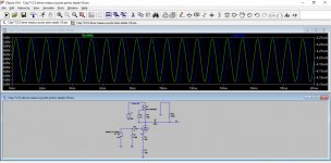
Hi gentlemen, I'm experimenting the use of a 10M45s on the plate of a 12AY7 and I had a bad discover. In both simulations and in practice, it seems that the CCS behaves electrically like a capacitor: voltage across it and flowing current are 90° shifted. This create 2 issues: 1. without a bypass capacitor on the cathode resistor, the cathode voltage is 90° the voltage on the grid; 2. it generates a capacity on the oulet of the stage, making it impossible to go over 15kHz -3dB. Any experience by your side?
Hi gentlemen, I'm experimenting the use of a 10M45s on the plate of a 12AY7 and I had a bad discover. In both simulations and in practice, it seems that the CCS behaves electrically like a capacitor: voltage across it and flowing current are 90° shifted. This create 2 issues: 1. without a bypass capacitor on the cathode resistor, the cathode voltage is 90° the voltage on the grid; 2. it generates a capacity on the oulet of the stage, making it impossible to go over 15kHz -3dB. Any experience by your side?
Attachments
andreuc,
I use the 900V IXYS part. I will have to take a look again at the frequency response of the single stage.
But, whenever I use that part, the whole amplifier with 2 stages (and no negative feedback) is good. No more than -1.5dB @ 20kHz for the whole amplifier.
It is not bad, like what you are getting with your circuit.
I do use 12AY7 tubes.
Give me a few days, I will take a look, if one of my amplifiers has that configuration,
then I will measure the one stage by itself.
I use 100 Ohms for the gate stopper of the IXYS part.
I use 1k Ohms for the grid stopper of the 12AY7.
I agree, -3dB at 15kHz is very bad.
I can not read your schematic, too small, low resolution.
What are the values of your IXYS gate stopper, and the two Source current sense/set resistors?
Last edited:
It has no plate load and source is applied between grid and cathode. What provides the gain?
The tube, obviously. The current changes proportionally to gm and grid-cathode voltage change. That causes voltage change on the load proportionally to it's resistance.
OK, if I may George, how does using a TX coupled, parafeed stage avoid blocking? The coupling cap is just on the other side of the TX.
cheers,
Douglas
cheers,
Douglas
Attached you can find a pdf with several simulations and real measurements. Simulations are done with the model of the 900V IXYS, but in my circuit I have the 450V one. In page one you can see the resistor values. Bias is 3V on the cathode with around 4.2mA from the CCS. At page 5 you can see that simulated values match nicely with real measurements, with both 12AY7 and 12AU7. At 20kHz the values diverge a lot. I don't knw if it's due to the unprecise model of the 10M90 or if '90 and '45 are really different in terms of how they behave like a capacitor. At page 6 I simulated a different CCS, with a PNP. At page 7 the graphos of voltage VS current on the 2 versions of CCS are shown. It's evident that the 10M90 behaves like a capacitor, being voltage and current shifted by 90°. In the latest page you can see the frequency response comparison (simulated) between the 2 CCS versions. Your comments and experiences are more than welcome, tnx.
andreuc,
I use the 900V IXYS part. I will have to take a look again at the frequency response of the single stage.
But, whenever I use that part, the whole amplifier with 2 stages (and no negative feedback) is good. No more than -1.5dB @ 20kHz for the whole amplifier.
It is not bad, like what you are getting with your circuit.
I do use 12AY7 tubes.
Give me a few days, I will take a look, if one of my amplifiers has that configuration,
then I will measure the one stage by itself.
I use 100 Ohms for the gate stopper of the IXYS part.
I use 1k Ohms for the grid stopper of the 12AY7.
I agree, -3dB at 15kHz is very bad.
I can not read your schematic, too small, low resolution.
What are the values of your IXYS gate stopper, and the two Source current sense/set resistors?
Attachments
Looking at your picture # 10, it seems that the transistor current source is a lower dynamic resistance than the IXYS current source.
Given that the resistance is lower for the BJT than the IXYS, and that lower resistance is in parallel with any capacitance, then the bandwidth will be larger for the BJT than for the IXYS.
The BJT low impedance "hiding" the capacitive reactance.
BJT 28.4 dB gain
IXYS 58.4 dB gain
That is a difference of 30dB at mid frequencies, where the different dynamic impedance of the 2 current sources is the only controlling factor of gain (mid freq, not high freq, and not low freq)
Do you see the difference?
The BJT dynamic impedance as seen at mid frequencies is also the same at high frequencies, so it is swamping out any capacitive reactance at high frequencies.
As you already know, a bypass cap in the cathode self bias circuit will increase both the gain, and the bandwidth of that circuit.
I know, some are very afraid of the "Ugly" sound of capacitors . . . another discussion for another thread.
Last edited:
If you want more bandwidth out of the 12AY7 and IXYS combination, then use the 12AY7 in parallel.
I have done that.
The original -3dB bandwidth frequency becomes the -1dB bandwidth at the same frequency (15kHz in your case).
But you have to do several things:
Double the IXYS current setting
Use a 1k resistor on the IXYS gate
Individual 12AY7 Grid Stopper resistors (use 1k, not the low resistance you are now using)
Use individual self bias resistor string for each cathode
Put a 1k series resistor in each plate
Join the other end of the 1k resistors at the IXYS current source.
How do I know this (I have done it, failure to take care of parallel 12AY7 triodes and IXYS combination can end up oscillating).
Good luck and happy building!
Last edited:
I realized just after sending the post that the picture #10 was wrong, due to the difference ac settings in the simulation between the 2 circuits. Matching the same source AC level, the amplitudes are very similar. Sorry for the inconvenience. The low frequency impedance of the BJT is a bit lower than the one of the 10Mxx, but it doesn't add any capacitive behavior, as shown in picture #7. How is the amplification factor of your 12AY7 stage?
Looking at your picture # 10, it seems that the transistor current source is a lower dynamic resistance than the IXYS current source.
Given that the resistance is lower for the BJT than the IXYS, and that lower resistance is in parallel with any capacitance, then the bandwidth will be larger for the BJT than for the IXYS.
The BJT low impedance "hiding" the capacitive reactance.
BJT 28.4 dB gain
IXYS 58.4 dB gain
That is a difference of 30dB at mid frequencies, where the different dynamic impedance of the 2 current sources is the only controlling factor of gain (mid freq, not high freq, and not low freq)
Do you see the difference?
The BJT dynamic impedance as seen at mid frequencies is also the same at high frequencies, so it is swamping out any capacitive reactance at high frequencies.
As you already know, a bypass cap in the cathode self bias circuit will increase both the gain, and the bandwidth of that circuit.
I know, some are very afraid of the "Ugly" sound of capacitors . . . another discussion for another thread.
Attachments
- Home
- Amplifiers
- Tubes / Valves
- IXYS 10M45S CCS for 6E5P tube driver