IXYS 10M45S CCS for 6E5P tube driver
Hi, i have an 6E5P KT88 triode amp with resistor load for 6E5P.
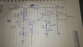
I will change and will use a 10M45S CCS.
Somebody know about resistors values of the resistors to have 25-30mA current.
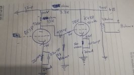
I put the present diagram with load resistance 6E5P and the future diagram with CCS 10M45S for 6E5P.
Hi, i have an 6E5P KT88 triode amp with resistor load for 6E5P.
I will change and will use a 10M45S CCS.
Somebody know about resistors values of the resistors to have 25-30mA current.
I put the present diagram with load resistance 6E5P and the future diagram with CCS 10M45S for 6E5P.
Attachments
According to one of the data sheets, a Log Log graph shows about 26mA with a kathode sense resistor of 100 Ohms.
85 Ohms should give you about 30mA.
I suggest you also try using a 100 Ohm gate stopper resistor, especially if you have oscillation.
At 26mA and 75V drop in your driver circuit you will have about 2 Watts of dissipation.
I suggest that you use a heat sink, especially if you are putting the current source in a closed amplifier chassis.
I always use a 100 Ohm Gate Stopper Resistor, but I use much higher resistance in the kathode sense resistor, about 410 Ohms to give me about 7 mA.
I now use the 900V IXYS part, because some of my amplifiers have turn on B+ voltages greater than 450V.
By the way, your first schematic with the 3V bias across your 220 Ohm self bias resistor is only 13.6 mA.
A 200 Ohm kathode sense resistor will set the IXYS part to put out about 14ma, much closer to what you have in the first schematic.
Check your voltages, currents, resistors, and calculations, some do not agree.
If you want the 6E5P to have 3V self bias and 26mA, you need a 115 Ohm self bias resistor.
Last edited:
You can use a potentiometer (temporary) in your 10M45S (kathode) in series with a 100 Ohm resistor. Then you can test and measure which current setting suits you best and place a fixed resistor then with the right value.
Regards, Gerrit
Regards, Gerrit
All of my designs, some dating back 15+ years to the introduction of the 10M45 have used a 1K resistor for the gate stopper.
Maybe the new parts are better, but the original parts made 15 years ago would oscillate relentlessly without a stopper which was never mentioned on the data sheet. Some point to point wired designs still oscillated with 100 ohms, so I went to 1K and have never seen reason to change it.
Every batch of 10M45's is slightly different. In my case 330 ohms gets me 8.5 to 11 mA which is good for 5842's (TSE amps) and 12AT7's (SSE amps). All other circuits get tuned up with a 1K pot, then the pot gets replaced by a fixed resistor.
Thanks you Tubelab.
And, do you know , if would be a good option use CCS and Transformer Interestage (Lundahl) coupling between 6E5P and KT88 ?
Now i am using Capacitor coupling ( Mundorf Silver Gold Oil ) without CCS.
And, do you know , if would be a good option use CCS and Transformer Interestage (Lundahl) coupling between 6E5P and KT88 ?
Now i am using Capacitor coupling ( Mundorf Silver Gold Oil ) without CCS.
I have never been a fan of interstage transformers since good ones cost a good deal of money.
If you choose to go this route, you would not use a CCS with a transformer in the typical circuit. You could use the CCS as the plate load, and then feed the transformer with the capacitor in a parafeed configuration. This could work out pretty good to eliminate blocking and offer a low DRC from the KT88 grid to ground.
If you choose to go this route, you would not use a CCS with a transformer in the typical circuit. You could use the CCS as the plate load, and then feed the transformer with the capacitor in a parafeed configuration. This could work out pretty good to eliminate blocking and offer a low DRC from the KT88 grid to ground.
I use the 10M45S with 100 Ohm Gate resistor and 100 Ohm + 1 KOhm pot. I have no experience with “old” production ones, and so far stability is perfect.
Regards, Gerrit
Regards, Gerrit
Tubelab_com,
Thanks!
I trust your judgement.
A 1k gate stopper works for you.
You would have noticed by now if 1k caused a high frequency roll off.
From now on, I will always use a 1k gate stopper there (Oh, I use the 900V IXYS part now).
Thanks!
I trust your judgement.
A 1k gate stopper works for you.
You would have noticed by now if 1k caused a high frequency roll off.
From now on, I will always use a 1k gate stopper there (Oh, I use the 900V IXYS part now).
That would be the IXCP10M90S probably. How is the 30K ohm "dynamic resistance" property to be understood, as an internal voltage change opposing a current change in the load? Is that enough to isolate a noisy PS from a 100X amplification stage? https://ixapps.ixys.com/DataSheet/DS98729A(IXCP-CY10M90S).pdfI now use the 900V IXYS part, because some of my amplifiers have turn on B+ voltages greater than 450V.
painted,
I do not set the 900V part for 100mA (OV g-k)
The impedance of the 900V part is far more than 30k for moderate currents.
Look at graphs # 5 & #7. g-k = 0V (0 Ohms). The part is turned on fully.
As you can see, keeping the part cool helps even for that extreme condition.
Depending on the temperature, 20mA requires 2.5V to 3.0V bias across the cathode to the return connection Sense resistor (about 125 to 150 Ohms).
If I remember correctly, I use 410 Ohms and get about 6 - 7mA. The impedance is extremely high all the way to 20kHz and beyond.
Look at graph # 2 & # 4 in the data sheet, to estimate the resistor you will need to start with.
Last edited:
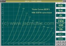
I am examining this valve for a simple 25x amplification. Looking at these triode curves it takes over 30mA for optimal operation.Are you going to use the 6E5P in triod mode?
OK, double that for 30mA current. Would it isolate my 'busy' PS (impedance of 20 ohm?) well enough (like 70dB above 10KHz) to saveguard the low Ri anode of circa 1.000 ohms?The impedance of the 900V part is far more than 30k for moderate currents.
Attachments
painted,
Your schematic is a cathode follower. The gain is less than Unity (<1).
To get gain of 25x from a triode, you have to take the output from the plate.
Your schematic is a cathode follower. The gain is less than Unity (<1).
To get gain of 25x from a triode, you have to take the output from the plate.
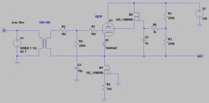
I understand this circuit to deliver 100 Vpp, with the 2nd harmonic down 60dB. That's with 2.5 Vpp input.
That would be the IXCP10M90S probably. How is the 30K ohm "dynamic resistance" property to be understood, as an internal voltage change opposing a current change in the load?
That is correct. Actually IXYS CCS device does not behave well with current higher than 10mA. Dynamic resistance decreases with increasing of current. Thus IXYS CCS is best for use in input stages of the amplifier, where current is low.
painted,
Please build it exactly as per the schematic.
Then let us know.
Maybe my gears are out of whack.
Please build it exactly as per the schematic.
Then let us know.
Maybe my gears are out of whack.
Thanks AVP, the answer I was looking for.
Mr Summer perhaps it takes some imagination but in effect you are looking at a penthode here, constructed from a triode with the aid of silicon. The purpose is to better the 4% distortion I am offered by my present solution 😉
Mr Summer perhaps it takes some imagination but in effect you are looking at a penthode here, constructed from a triode with the aid of silicon. The purpose is to better the 4% distortion I am offered by my present solution 😉
Attachments
Last edited:
Can anybody look at the circuit as drawn in Post # 12, and figure the gain?
Perhaps the screen is driving the top current source, and the current source is the output stage, like a follower.
Does the gain equal the tube g1 to g2 mu (u)?
And does the signal output drive the whole input transformer secondary up and down, driving / slewing the primary to secondary capacitance?
. . . My head hurts.
I guess I am missing something.
I need to update my circuit analysis skills.
Help, please.
Thanks!
Last edited:
painted,
Your schematic is a cathode follower. The gain is less than Unity (<1).
To get gain of 25x from a triode, you have to take the output from the plate.
No, it is not. This is a gain stage with cathode load. But I am not sure that the part that supplies screen voltage should use CCS device instead of simple transistor. Even then it looks like having positive feedback.
Also the circuit will be very sensitive to temperature changes. It is never a good idea to use CCS in series with tetrode.
Last edited:
- Home
- Amplifiers
- Tubes / Valves
- IXYS 10M45S CCS for 6E5P tube driver