An externally hosted image should be here but it was not working when we last tested it.
Some real ugly rats-nest wiring...
All components are on the board.
Very neat Elvee 😀 I easily saw the current protection provided by the 0.1 ohm resistor in the positive rail, then i saw the negative rail protection provided by R26/37 & the base of Q11 😉This my final (lab) version, including a latching protection.
I am currently adapting the topology for very high voltage output (>1KVpp).
I'm sure a lot of people would be interested in a high voltage version, myself included. No real idea what i'd ever use it for but on the other hand 1KV+ amplifiers aren't exactly common, it'd be educational to say the least.
I have followed this thread from the moment i stumbled upon it, keep up the good work chap. I'm sure i'm not the only one getting ideas from it, just thought i'd let you know that it's appreciated 🙂
Krohn Hite 7500 schematic
Per Request (it took some searching to find) here it is, some serious high voltage with bandwidth- 500 KHz full power at 100V RMS., 140 V RMS open circuit, 75 Watts.
http://pws.prserv.net/demian/Krohn-Hite/Krohn-Hite-7500.pdf
Per Request (it took some searching to find) here it is, some serious high voltage with bandwidth- 500 KHz full power at 100V RMS., 140 V RMS open circuit, 75 Watts.
http://pws.prserv.net/demian/Krohn-Hite/Krohn-Hite-7500.pdf
Per Request (it took some searching to find) here it is, some serious high voltage with bandwidth- 500 KHz full power at 100V RMS., 140 V RMS open circuit, 75 Watts.
http://pws.prserv.net/demian/Krohn-Hite/Krohn-Hite-7500.pdf
Wow!!!
Pretty impressive, and awe inspiring.
Building such an amplifier out of BJT's really is an uphill struggle.
Most of those transistors have become very hard to find. And expensive. Notice the stack of transistors in the driver stage. My last price on these was around $5.00 ea.
The amp I have here is broken and I'm not sure how yet. It has blown fuses. I have been reluctant to fire it up with the high voltages in it and the potential for unpleasant experiences. I'll confront it on a long quiet weekend. I may well sell it once its working since I don't really need it and they still fetch a lot of money (over $2K) given very few other solutions to that problem.
The amp I have here is broken and I'm not sure how yet. It has blown fuses. I have been reluctant to fire it up with the high voltages in it and the potential for unpleasant experiences. I'll confront it on a long quiet weekend. I may well sell it once its working since I don't really need it and they still fetch a lot of money (over $2K) given very few other solutions to that problem.
Are there any news?This my final (lab) version, including a latching protection.
I am currently adapting the topology for very high voltage output (>1KVpp).
1audio: thank you very much for the schematic-PDF about post#65
Are there any news?
I have defined the architecture, and I am now in the process of selecting suitable devices.
So far, I have found this one from ST:
http://www.st.com/stonline/products/literature/ds/13539/stw9n150.pdf
I would like to find some alternatives, and I also need lower power devices (including bipolars) for the driver stages.
If someone has references handy, they are welcome.
Here some threads regarded MOSFETs:I have defined the architecture, and I am now in the process of selecting suitable devices.
So far, I have found this one from ST:
http://www.st.com/stonline/products/literature/ds/13539/stw9n150.pdf
I would like to find some alternatives, and I also need lower power devices (including bipolars) for the driver stages.
If someone has references handy, they are welcome.
http://www.diyaudio.com/forums/solid-state/23526-best-mosfet-output-stages.html
http://www.diyaudio.com/forums/pass-labs/99132-aleph1-2-irf240-vs-irfp250.html
http://www.semelab.com/magnatec/alfet.shtml
IXYS RF: HF/VHF Linear MOSFETs
http://www.diyaudio.com/forums/pass...p120r100-sjep170r550-better-building-amp.html
http://www.diyaudio.com/forums/group-buys/153759-ixth20n50d-depletion-mode-mosfet-group-buy.html
http://www.diyaudio.com/forums/pass-labs/6461-irf-3-devices-75-a.html
http://www.diyaudio.com/forums/tubes-valves/121556-tubelabse-best-mosfet-choice.html
http://www.diyaudio.com/forums/solid-state/141001-what-mosfets-use.html
and BjT's for driving requirement:
http://www.diyaudio.com/forums/soli...ver-stages-high-power-amplifier-overview.html
http://www.diyaudio.com/forums/soli...bd159-gbp-transit-frequency-ft-unknown-3.html
http://www.diyaudio.com/forums/soli...istor-families-audio-power-output-stages.html
http://www.diyaudio.com/forums/soli...0-bd159-gbp-transit-frequency-ft-unknown.html
Last edited:
I should have made clear that I was looking for very high voltage devices. In this respect, the SJEP170R550 from Semisouth is marginally better than the ST.
For the small to medium power bipolar, I was trying to find something similar to the BUX87, but higher voltage, and more suitable for linear operation.
Thanks for the pointers anyway, the SiC looks promising.
For the small to medium power bipolar, I was trying to find something similar to the BUX87, but higher voltage, and more suitable for linear operation.
Thanks for the pointers anyway, the SiC looks promising.
I recall to some BjT high voltage types from Shindengen but on the currently website I don't find such types:
Home | SHINDENGEN ELECTRIC MFG.CO.,LTD
perhaps there you will find appropriate types:
Description TRANSISTOR, TRANSISTOR Datasheet search, TRANSISTOR datasheet, TRANSISTOR datasheets, TRANSISTOR data sheets - ALLDATASHEET.COM
the follow is made prefer for switching application (HFX Series):
http://www.datasheetcatalog.org/datasheet/Shindengen/mXrwvs.pdf
but the question is whether it is only suitable for switch applications
There are some other HV BjTs, but except the MJ16018 MJ16018 pdf, MJ16018 description, MJ16018 datasheets, MJ16018 view ::: ALLDATASHEET :::
I don't know types for linear applications:
2SC3996 pdf, 2SC3996 description, 2SC3996 datasheets, 2SC3996 view ::: ALLDATASHEET :::
BUH1215 Datasheet pdf - HIGH VOLTAGE FAST-SWITCHING NPN POWER TRANSISTOR - SGS Thomson Microelectronics
BUY71 pdf, BUY71 description, BUY71 datasheets, BUY71 view ::: ALLDATASHEET :::
by post #32 about
http://www.diyaudio.com/forums/soli...8-2sk60-2sj26-2sk76-2sk180-4.html#post2152954
there are informations about various patents concerning SIT's - perhaps also of interest here
http://www.diyaudio.com/forums/soli...8-2sk60-2sj26-2sk76-2sk180-4.html#post2152954
there are informations about various patents concerning SIT's - perhaps also of interest here
could you perform a stability test so as an audible test already?This my final (lab) version, including a latching protection.
I am currently adapting the topology for very high voltage output (>1KVpp).
here a solution for a passive phase reverse stage (i. e. with interstage transformer resp. driver transformer instead a totem pole common emitter or emitter follower topology):
http://www.diyaudio.com/forums/pass-labs/216616-f6-amplifier.html
http://www.diyaudio.com/forums/pass-labs/216616-f6-amplifier.html
Last edited:
It takes me back 40yrs: I remember building such an amplifier, transformer-less output based on AD149's, and at the time I found the sound amazingly good...here a solution for a passive phase reverse stage (i. e. with interstage transformer resp. driver transformer instead a totem pole common emitter or emitter follower topology):
http://www.diyaudio.com/forums/pass-labs/216616-f6-amplifier.html
Hi Elvee!
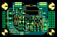
I have this little beast on my todo list for quite some time now and finally got around to route a little layout for it. It is single layer only with thicker tracks suitable for home etching, but still fairly compact with 8x5cm (you get four pieces from a single Euro card 😎). Would you consider this as suitable for your amp wrt loop area / stability etc.? I've opted for horizontal 5W concrete resistors, since I neither like smaller 2W'ers running too hot, nor those big 5W'ers standing vertical due to mechanical instability. C3 can be either a cheap electrolytic or a foil type like WIMA MKS 2. The double footprints for the MOSFETs are only there for some freedom in mounting, they're not supposed to take two in parallel each! To make some use of the free space between the mounting holes (any amp board absolutely needs mounting holes) I've added some 'perfboard' for some additional botching (like adding an input cap for example), which might come in handy for a lab workhorse lying bare on the workbench...
Your latest version with protection and all the bells and whistles looks interesting, too, but I'd like to start out with the simple one first 😉.
Best regards,
Lasse
Attachments
Hi Lasse,
Sorry for the the late response, but this thread fell out of my subscribed threads for some reason, and I have just stumbled on your contribution only now, whilst searching for something else.
Your PCB seems to be very much to be in the spirit of the project: nice clever and compact, and I think it will perform quite adequately.
Depending on the actual MOS type used, the diode string setting the gate voltage and quiescent current may need to be adapted, in length and diode type: zener, schottky or regular, to arrive at an acceptable Iq.
That is one of the main weaknesses of the scheme: find the correct combination with discrete components. Somewhat more finnicky than adjusting a trimmer (but much more stable once it is done)
Thanks for the heads-up! 🙂
Maybe I should try to beef up the pads for the diode string a little then, so they don't wear out too fast due to repeated unsoldering...
No problem with your late response, since I just happen to be 'back on line' since yesterday. Had to wait for my new FTTH due to relocation and it took almost three months 😱!
- Status
- Not open for further replies.
- Home
- Amplifiers
- Solid State
- It's cheap, it's N, it's dirty, it's.... The CIRCLOMOS!!!