Has anyone tried this r2r dac from an Italian guy?
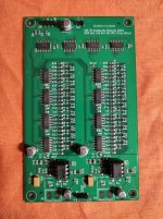
It uses only discrete logic - (74hc74 and 74hc595) so no cpld or dsp) and stops the clock after the data is transferred. It came with TL082 opamps which will be replaced with LME49720 or OPA2134.
The price is low enough for me to buy one but haven't tried it yet as I haven't finished assembling my LiPO4 power supply.
I2s source is from a standard DIR9001 spdif interface.
https://www.ebay.co.uk/itm/325231264279
I will shortly be doing a comparison of my dual TDA1541 dac, my quad balanced AD1862 and the above and also a Cambridge Audio Azur 651c Cd player (TDA1305 continuous calibration dac) and a Cambridge Dacmagic 1 (two WM7840 in balanced configuration).
Will my ancient ears be able to hear any difference!
Attachments

Stopped clock is a different protocol from I2S, although the term I2S is sometimes used to refer to the hardware bus rather than the digital audio data transfer protocol. Reason I ask is because IIUC most SPDIF receivers and USB boards I am aware of do not support stopped a stopped clock protocol. Maybe I2SoverUSB can do it, not sure. http://jlsounds.com/i2soverusb.html...stops the clock after the data is transferred.
Other than that, the sound this type of dac produces may vary quite a bit depending on the particular implementation of the Vref voltage regulation and filtering. Also, clock jitter of the I2S source could be a factor affecting SQ, depending.
i thought the stopped clock might be similar to iancanada's I2S to PCM board. It's true that the Dir9001 doesn't support it.Stopped clock is a different protocol from I2S, although the term I2S is sometimes used to refer to the hardware bus rather than the digital audio data transfer protocol. Reason I ask is because IIUC most SPDIF receivers and USB boards I am aware of do not support stopped a stopped clock protocol. Maybe I2SoverUSB can do it, not sure. http://jlsounds.com/i2soverusb.html
Other than that, the sound this type of dac produces may vary quite a bit depending on the particular implementation of the Vref voltage regulation and filtering. Also, clock jitter of the I2S source could be a factor affecting SQ, depending.
Actually I re read the sellers description doesn't mention stopping the clock so ignore this. (must have read it in the description of one of thes everal r2r dacs on Aliexpress.)
I am using eight 8000ma/hr Lipo cells and a LT3042 very low noise regulator to provide the 5v for the ladder.
Last edited:
Vref could get regulated down from from the +12v supply. It should an analog power rail, not digital. Other than that, batteries can be useful for avoiding ground loops and or AC line noise incursion, but their ESR ratings by be only valid for rather low frequencies, not necessarily for the whole audio band. LT3042 is indeed low noise (if well implemented), but not necessarily a good sounding, nice, linear error amplifier in it. Sometimes opamp buffers sound better than voltage regulators for driving DAC Vref. Discrete shunt regulators might be optimal for that if well designed for the load. Low noise is important, but so is linear impedance with frequency, error amplifier linearity, etc. Most regulators start to look inductive to the load as frequency increases. IIRC a patent by ESS for shunt regulation for digital circuitry claims that shunt regulators are better than series regulators in that respect.
LT3042 is indeed low noise
Interesting. Every time i tried using one of these i ended up taking it out because of the horrible thin sound. Even a tl431 sounds better to me.
Nice find. Thanks for sharing your DAC adventures 🙂
The UK ebay description is in Italian so for others convenience Ive pasted an online translation below:
I2s to Analogue Ladder Converter Board PCB No CPU, No OS
- PCB board which makes I2S to stereo analogue output.
- A handful of TTL ports and an R2R ladder resistor network for the analogue output.
- Up to 24 bits are converted. At 16 bits the last 8 are zero, they do not work and are irrelevant.
- The two left and right channels are perfectly synchronized.
- Linearity is guaranteed by the resistors used with a tolerance of 0.1%.
- The integration section with classic OP Amp for a low pass to get 8vpp output.
- It comes with TL082 but you can mount any version you want, including discrete OP amps.
- The interface is totally in hardware there are no CPUs.
- It works in non-oversampling mode and accepts clock frequencies beyond the classic 44.1 Khz.
- 5V DC power supply for digital, +/- 12V DC for analogue.
- EUR 85.00
Every time i tried using one of these i ended up taking it out because of the horrible thin sound.
What value of Cset?
Something to watch out for and investigate other regulators - shunt type perhaps.Interesting. Every time i tried using one of these i ended up taking it out because of the horrible thin sound. Even a tl431 sounds better to me. I
I noticed that AN used multiple TL431s on their DAC 1, so this is a good advert for them.
How do you know that the recording you were listening to did not have a horrible thin sound which was veiled by the added noise of tl431?Interesting. Every time i tried using one of these i ended up taking it out because of the horrible thin sound. Even a tl431 sounds better to me.
I2s source is from a standard DIR9001 spdif interface.
Can I ask about jitter control in your new R2R DAC tests? I assume the R2R board has no clocks sand runs off the I2S?
Will you be clocking the DAC just from the DIR9001? The DIR9001 datasheet cites low jitter at higher sample rates. It might be worth upsampling in software to 96kHz. Foobar has some good free plugins in you run Windoze.
But a real world jitter test at 44.1 doesnt look so great
MEASUREMENTS: MUSE Mini TDA1543x4 NOS DAC
The DIR9001 digital receiver in this unit allows up to 24/96https://archimago.blogspot.com/2013/02/measurements-muse-mini-tda1543x4-nos.html
Do you have any other I2S sources with dedicated clocks?
Are there any equally affordable eBay USB-I2S boards to match your ebay R2R taht have XMOS and paired clocks with low jitter?
That 16/44 jitter test result does not look that bad as it is 16-bits so sidebands should be visible above -140dB.
Archimago himself wrote this:
"Looking at all those sidebands in the jitter plot, I'd estimate it to be >5ns; but yet it still sounds quite good! IMO, more evidence to say there's no point to quibble about the odd sidebands and whatever picosecond jitter found in well engineered gear..."
Archimago himself wrote this:
"Looking at all those sidebands in the jitter plot, I'd estimate it to be >5ns; but yet it still sounds quite good! IMO, more evidence to say there's no point to quibble about the odd sidebands and whatever picosecond jitter found in well engineered gear..."
I'll be using it with 44.1 and 48kHz fs and the jitter is around a claimed 50ps so not worth trying something more sophisticated.Can I ask about jitter control in your new R2R DAC tests? I assume the R2R board has no clocks sand runs off the I2S?
Will you be clocking the DAC just from the DIR9001? The DIR9001 datasheet cites low jitter at higher sample rates. It might be worth upsampling in software to 96kHz. Foobar has some good free plugins in you run Windoze.
View attachment 1093395
But a real world jitter test at 44.1 doesnt look so great
MEASUREMENTS: MUSE Mini TDA1543x4 NOS DAC
The DIR9001 digital receiver in this unit allows up to 24/96
View attachment 1093387
https://archimago.blogspot.com/2013/02/measurements-muse-mini-tda1543x4-nos.html
Do you have any other I2S sources with dedicated clocks?
Are there any equally affordable eBay USB-I2S boards to match your ebay R2R taht have XMOS and paired clocks with low jitter?
View attachment 1093411
However I use Iancanada's Fifo II, clock board and I2S to PCM for my dual 1541 dac so I can swap the dac board over and compare.
I've just bought two more I2s to PCM boards, one for my quad AD1862 dac and perhaps I'll try the other between the DIR9001 and the ladder dac.
It seems that the ladders uses a lot of current from the 5v supply so not possible to use the LT3042 or TL431. Need a 2a low noise supply - eg LM338 or discrete regulator.
HiHas anyone tried this r2r dac from an Italian guy?
I did not try this specific model
But I build one, (no fpga/cpld), ladder R2R DIP logic gates 32bit dac.
I can say that even with 1% worst case MF resistors sound is very good.
trimming of MSB and MSB-1 was welcome, BUT not solved the -xxdb dist issues. Because of temperature chnage.
It was Left justified format input.
...
Low tolerance R are the must for these type of dacs
However I use Iancanada's Fifo II, clock board and I2S to PCM for my dual 1541 dac so I can swap the dac board over and compare.
I've just bought two more I2s to PCM boards, one for my quad AD1862 dac and perhaps I'll try the other between the DIR9001 and the ladder dac.
Youve got the best I2S delivery. Great. Thanks for swapping them around. All three I2S boards may sound different, regardless of jitter specs.
It has been known for a long time that some types of jitter effects can help mask other problems in audio equipment. Perceptually the effect can be that the jitter makes it sound better (that is to say, more tolerable) than it would without the jitter. It doesn't seem like very good evidence in support of an argument that its fine to ignore jitter."Looking at all those sidebands in the jitter plot, I'd estimate it to be >5ns; but yet it still sounds quite good! IMO, more evidence to say there's no point to quibble about the odd sidebands and whatever picosecond jitter found in well engineered gear..."
What effect does jitter have on audio quality? I.e how would I know that excessive jitter is having an adverse effect?It has been known for a long time that some types of jitter effects can help mask other problems in audio equipment. Perceptually the effect can be that the jitter makes it sound better (that is to say, more tolerable) than it would without the jitter. It doesn't seem like very good evidence in support of an argument that its fine to ignore jitter.
0.1% resistors are fitted.Hi
I did not try this specific model
But I build one, (no fpga/cpld), ladder R2R DIP logic gates 32bit dac.
I can say that even with 1% worst case MF resistors sound is very good.
trimming of MSB and MSB-1 was welcome, BUT not solved the -xxdb dist issues. Because of temperature chnage.
It was Left justified format input.
...
Low tolerance R are the must for these type of dacs
The way we have done it here is to perform listening tests with various clocks where the clocks can be switched almost instantly for A/B comparisons. We have also shown that increased clock power supply noise affects perceived sound and imaging. However, it takes a very good dac (and an overall good reproduction chain) to be clean enough so that small differences in clocking can be heard. Many dacs have enough SQ problems that clocks are one last things that needs fixing. It also may depend on the operating mode of a DAC. DSD is known to be more jitter sensitive than PCM. OTOH PCM has other problems such as, for one example, element matching. 0.05% resistors may seem pretty good because most resistors are much worse than that. 0.05% isn't necessarily good enough for a very high performance dac though. Some dacs use oversampliing and 'scrambling' techniques to help average out component matching problems. https://ieeexplore.ieee.org/document/5420027What effect does jitter have on audio quality? I.e how would I know that excessive jitter is having an adverse effect?
EDIT: Regarding the first question about what effect does jitter have on SQ, IMHO it can very a lot depending on the exact time-domain variation in clock phase and or frequency. In other words we could plot clock phase as a function of time and then probably find some correlation between that and perceived SQ. Problem is that measuring phase verses time for a very low close-in phase noise clock would not be simple. Something like a Timepod uses averaging techniques to measure very low close-in phase noise so it wouldn't help for measuring phase as a function of time.
Possibly helpful document attached.
Attachments
Last edited:
You should be a bit more careful about quoting as your post #15 looks like you are quoting me but it was actually a quote from Archimago.It has been known for a long time that some types of jitter effects can help mask other problems in audio equipment. Perceptually the effect can be that the jitter makes it sound better (that is to say, more tolerable) than it would without the jitter. It doesn't seem like very good evidence in support of an argument that its fine to ignore jitter.
- Home
- Source & Line
- Digital Line Level
- Italian R2R ladder DAC, no CPID/DSP