Many people here have used a power transformer as an output transformer, so it seems. I was thinking about this, and particularly the voltage rating the primary winding should have. Say we have a transformer with two 120V primaries and we could connect them in series and it would run just fine with 240Vac across them at 50Hz. We might conclude that we could connect the transformer from one anode to the other and put HT to the junction of the two windings and with 240VRMS measured from anode to anode it should work just fine down to 50Hz. With continuous tone it probably would, but music is generally not continuous tone.
Say we put a 50Hz tone burst through the amplifier. The transformer would be driven first fully one way then fully the other way. The thing is, a transformer will only tolerate a half cycle of its rated voltage if it is swung from its negative rated voltage first. If the voltage is begun from the zero crossing the transformer will saturate halfway through the half cycle. Or putting it another way, if we apply a low frequency transient that starts at the zero crossing we can only apply half the transformer’s rated voltage. This is the cause of the “bump” a big power transformer makes when it gets switched on at the a ins zero crossing.
So for our 240V 50Hz rated transformer we can only pump it with 120VAC of 50Hz audio. That will produce only 1/4 of the power we could pass through it than if we were listening to continuous tones. Has anyone found this to be an issue in practice?
The magnetising current "bump" in a power trans happens because you don't start with the hysteresis curve in the neutral 0/0 center. In an OPT you have already set the hysteresis loop to its center during power on. Remember, PT are only good for push-pull, with center tap. If you look at things from the perspective of the center tap, the situation is no different than in a PT. When one end rises by 150v the other end drops by 150v, or 300v end to end ...
Last edited:
Output transformers are called output transformers due to their design. Mains transformers are called mains transformers due to their design. Different winding formulae and characteristics. Admittedly the humble toroid mains transformer works as an output matching transformer in solid state 100volt line amplifiers but they are employed after the output stage that is suitably protected with DC blocking if solid state or not used at all, if valve state.
A few people have done this for non-critical applications such as guitar amps and AM modulators. If you are interested in sound quality then this trick is not for you.Circlotron said:Many people here have used a power transformer as an output transformer, so it seems.
I guess the main issue is that of the lower expectations of eddy loss for a mains transformer over an audio grade device. For reasons of manufacturing economy, a mains transformer maker wants to use the thickest allowable laminations: fiddling with fewer laminations streamlines production markedly. Thinner ready-to-punch stock costs more when thinner, too.
Since eddy losses rise linearly with frequency (for a given lamination scheme), fewer thicker lams, good 'nuf for mains, negatively impacts deliverable power for the same transformers used in audio output applications.
The other significant difference is that of how the primary and secondary are physically wound. The majority of EI mains transformers either 2 layer co-wound, or separate section bobbin-wound. Either are fairly low-cost rapid-production techniques. Bobbin wound has hi-pot isolation advantages, but least-well-coupled primary-and-secondary mutual magnetic coupling. Co-wound has fairly good hi-pot isolation, but much better coil-coil magnetic coupling. It also is well adapted to 'no form' winding, or mandrel winding (parallel coil winding on long rectangular cross section shafts).
Contrast both of those techniques to audio-grade transformer winding. Very often, the 'center tapped' primary is bifilar-wound, with a pair of magnet wire windings carefully laid down side-by-side. Much pickier winding, I tell you from first hand experience. Likewise, the primary may be doubly split … ½ P, S then ½ P over that, for even better magnetic coupling. Pickier! And to further juice things up, the secondary also may be bifilar wound as 2 ea., 8 Ω windings. Series, 16 Ω. Singly, 8 Ω., and so on.
As KodaBMX has often rebutted, the above observations about EI power transformers are substantially upended with well-made, relatively commonplace toroidal mains transformers, asked to perform hi-fidelity audio-output service. The core lamination stock is usually a combination of higher 'grade' (maximum saturation, and magnetic 'hardness'), thinner (lower eddy losses) and physically WAY better at coërcing the magnetic field lines to remain in-core by being physically 'bent' into a circular form. Being curved (again on a mandrel) bends the silicon iron grains in a way impossible for an EI type transformer. Yet further, winding toroids lends itself to co-wound technique, and for bifilar winding.
So, your basic good-quality toroid is fairly well suited for audio output service.
The only things you need to do as a designer are to remember to over-spec them. If for instance you're planning on a 50 W output, the toroid should be at least a 150 VA unit, if not 200. This allows getting 'down to' the 20 to 30 Hz band without undue core saturation.
Don't expect too much tho' from the high frequency end. Again, hoping that KodaBMX will pop in, but above about 10 kHz, response drops off. Would be nice to hear more.
Just saying,
GoatGuy ✓
I used a 220 to * 250VAC + 6.3V for audio output using heater winding as the speaker coil and worked satisfactory. Also a 110+110/12+12V toroid was used from the plates of a couple of ECL82's with excellent results. (12V secondaries paralleled to 8Ω speakers).
I get flat response from ~25Hz to 50kHz with the Triad toroids... Use two, and wire them series interleaved.
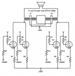
Here's an example using push pull parallel 6P45S tubes wired in triode. This output stage makes 112W @ 30Hz.
In this way, you don't need to overspec the transformers as much. If you want 50W, use two 50VA coils. Using only one of the coils, you get 112W at 50Hz, but only about 15W at 30Hz before saturation.
Attachments
Last edited:
I get flat response from ~25Hz to 50kHz with the Triad toroids… Use two, and wire them series interleaved.
Here's an example using push pull parallel 6P45S tubes wired in triode. This output stage makes 112W @ 30Hz.
In this way, you don't need to overspec the transformers as much. If you want 50W, use two 50VA coils. Using only one of the coils, you get 112W at 50Hz, but only about 15W at 30Hz before saturation.
Beautiful cross-symmetric primary design. The VPT 18–13800 has (as shown) 2 primaries, 2 secondaries, costs $60 apiece, and is 200 VA max-rated. Nominally, 115 + 115, 9 + 9. The net, connected as these are is (in voltage terms, which is aggregate turns-ratio terms) 230-to–36 or 6.38 to 1. Recalling that
ZPRI = ZSEC • ratio² …
ZPRI = 8 Ω × 6.38²
ZPRI = 325 Ω
Which got me scratching my head. Not exactly sure that's what you intended, right? I am probably missing something in regards to the cross-hooked primaries. ZPRI = 8 Ω × 6.38²
ZPRI = 325 Ω
Or maybe not! The +320 V supply (in diagram) will only realistically support ±295 V of swing in the push-pull configuration. This corresponds to what, 209 VRMS. Stepped down 6.38× to 32.7 VRMS. Which by P = E²/R … = 32.7² V / 8 Ω = 132 W…
Basically within 'shooting distance' of your claim.
Nice work.
Just saying,
GoatGuy ✓
Last edited:
The primary is connected in series, so ratio is 460-to-36 or 12.8 to 1. Z primary is about 1.3k for an 8 ohm secondary. To get 112W, Kodabmx must be using a higher B+ or lower load impedance.
So, your basic good-quality toroid is fairly well suited for audio output service.
The only things you need to do as a designer are to remember to over-spec them. If for instance you're planning on a 50 W output, the toroid should be at least a 150 VA unit, if not 200. This allows getting 'down to' the 20 to 30 Hz band without undue core saturation.
I've used custom-wound toroids to good effect as output transformers (driven by SS though, not valves). The over-speccing that's needed isn't on the VA its on the voltage on the primary - if you want to go down to 20Hz then you can only feed it 40% of the rated voltage at 50Hz or it'll likely saturate. The VA rating depends primarily on how much series resistance (copper losses) you're willing to tolerate. I've found toroids rated at 30VA to work well with an amp of roughly the same power output (30W). Conversely, in driving headphones I found I needed 10VA to keep the series resistance under control, even though the 'cans need a miniscule fraction of that power.
The primary is connected in series, so ratio is 460-to-36 or 12.8 to 1. Z primary is about 1.3k for an 8 ohm secondary. To get 112W, Kodabmx must be using a higher B+ or lower load impedance.
112W at 30Hz (or 1 kHz) was tested using a load of 6R. It uses 6P45S triode connected.
Also VPT18-13800 is rated at 250VA, not 200VA 🙂
Here's the full schematic:
Last edited:
some work ok, others don't it has to do with winding symmetry and core materials. line transformers can be made cheap. Some of the Antek torroids work well
I think most people missed the main point of my post.
Half the voltage that it would tolerate at that particular frequency if it were instead a continuous tone. That means only 1/4 the power output.
if we apply a low frequency transient that starts at the zero crossing we can only apply half the transformer’s rated voltage.
Half the voltage that it would tolerate at that particular frequency if it were instead a continuous tone. That means only 1/4 the power output.
Last edited:
I think most people missed the main point of my post.
Half the voltage that it would tolerate at that particular frequency if it were instead a continuous tone. That means only 1/4 the power output.
I don't think toroidal power transformers (used within normal voltage limits) would be any different to regular output transformers regarding this, I can't imagine the vendors doubling turns just for these transient events. Do such transients actually exist in music and would you notice saturation for a half cycle anyway?
Not in my testing. Sounds better than Hammond IMHO.
i tried toroids in parafeed, it was really ok. not much luck with EI
- Home
- Amplifiers
- Tubes / Valves
- Issues with using power transformer as output transformer