I bought this B&K Reference 125.7 amp with 6 out of 7 channels working.
Have been looking for this or the 200.7 for 3-4 years and knew I could only afford one if it had a bad channel or two. They are still bringing decent money some 20-years later.
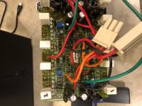
The blown channel had actually blown off the traces where the lateral mosfet had shorted at the gate resistor. So I tested all the remaining 6 channels and they were working fine. And went about replacing all 4 output FETs with Exicons, matched best I could with the 8 I had on hand (all of them were quite close).
Powered up and was not getting drive to the outputs, so I ordered new drivers BJTs (2n3440 and 2n5416) from Mouser. Even though they tested good out of circuit. Installed the new parts and that channel was working.
Bad news - while testing why the outputs were not getting drive, I shorted a resistor and blew a trace off a working channel, as well as the negative side rail fuse for that same channel.
Repaired the traces, resistor and tested all pre-drivers, replacing any that tested as bad (I think there was 3 on one channel and 2 on another).
Now it was working 100%:
All Channels working and set bias and played for over a week off and on - probably 20-30 hours in total at normal listening levels. I also dummy load tested each channel at 70% power on my O-Scope and all channels looked to be working. Sine was smooth, clipped as expected and got about 185W at 8r and 235W at 4r on all 7 channels.
More Bad news - and a weird happening:
I put the amp in my HT rack, with brand new XLR cables and watched 2-3 movies and my son played xBox for about a week. After about a week, I finished watching a movie with my son and I wanted to feel how hot the amp was getting and make sure ventilation was adequate.
I touched the top of the case and heard a "crackle" (a small 1-2 second buzz, then pop) through one channel (Right surround). The case was warm but not hot at all, probably 35-40C, which is slightly more than is ran on my test bench for a week.
I turned it off and when I turned it back on 2-3 minutes later to see if the "crackle" was still there - DC out of that same right-surround channel and before I could turn it off, it had a loud BUZZZZZ and blew the woofer (5-1/4") in that surround speaker. Now that channel is dead - no DC being output?
I pulled the amp, tested all the other channels (they all work fine) and this channel was a working channel when I bought the amp, but was one of the effected channels by my "mis-hap" with the DMM probe.
Long way around to the questions:
- I have tested the (2SK1058/2SJ162 - 1 pair each) outputs and they test fine, both with DMM out of circuit and 2 different eBay testers
- I have tested the drivers (2n3440/2n5416) and the only strange thing compared to a new part is the old parts Ic=6mA, where new part tests Ic= 1mA, this on the eBay testers, not an actual test jig though.
- I have tested all the pre-drivers and they all tested within spec. I also verified all resistors and diodes are in spec. and working, pulled the caps and verified with a tester within spec. All rail voltages are within spec too.
- Is this possible that the drivers going bad, could cause DC on the output and fry my woofer? Then blow the channel without harming the outputs or blowing a fuse?
Any assistance would be appreciated, as I'm confused why on the drivers are testing bad and would do anything but not turn-on the outputs?
I have new parts coming this weekend, but I can't find an exact schematic (there are similar versions with different FETs, but not exact), but doesn't appear to be very complex design either. The only strange part is it has +/-65V (red/black) going to the 4 channel board, and also has +/-65V (Red/Orange/Black) along with Ground (Green). Not sure why it needs two wires carrying the same rail voltage, but I think it is a mute circuit possibly, testing if there is full rail voltage (guessing though).
Have been looking for this or the 200.7 for 3-4 years and knew I could only afford one if it had a bad channel or two. They are still bringing decent money some 20-years later.
The blown channel had actually blown off the traces where the lateral mosfet had shorted at the gate resistor. So I tested all the remaining 6 channels and they were working fine. And went about replacing all 4 output FETs with Exicons, matched best I could with the 8 I had on hand (all of them were quite close).
Powered up and was not getting drive to the outputs, so I ordered new drivers BJTs (2n3440 and 2n5416) from Mouser. Even though they tested good out of circuit. Installed the new parts and that channel was working.
Bad news - while testing why the outputs were not getting drive, I shorted a resistor and blew a trace off a working channel, as well as the negative side rail fuse for that same channel.
Repaired the traces, resistor and tested all pre-drivers, replacing any that tested as bad (I think there was 3 on one channel and 2 on another).
Now it was working 100%:
All Channels working and set bias and played for over a week off and on - probably 20-30 hours in total at normal listening levels. I also dummy load tested each channel at 70% power on my O-Scope and all channels looked to be working. Sine was smooth, clipped as expected and got about 185W at 8r and 235W at 4r on all 7 channels.
More Bad news - and a weird happening:
I put the amp in my HT rack, with brand new XLR cables and watched 2-3 movies and my son played xBox for about a week. After about a week, I finished watching a movie with my son and I wanted to feel how hot the amp was getting and make sure ventilation was adequate.
I touched the top of the case and heard a "crackle" (a small 1-2 second buzz, then pop) through one channel (Right surround). The case was warm but not hot at all, probably 35-40C, which is slightly more than is ran on my test bench for a week.
I turned it off and when I turned it back on 2-3 minutes later to see if the "crackle" was still there - DC out of that same right-surround channel and before I could turn it off, it had a loud BUZZZZZ and blew the woofer (5-1/4") in that surround speaker. Now that channel is dead - no DC being output?
I pulled the amp, tested all the other channels (they all work fine) and this channel was a working channel when I bought the amp, but was one of the effected channels by my "mis-hap" with the DMM probe.
Long way around to the questions:
- I have tested the (2SK1058/2SJ162 - 1 pair each) outputs and they test fine, both with DMM out of circuit and 2 different eBay testers
- I have tested the drivers (2n3440/2n5416) and the only strange thing compared to a new part is the old parts Ic=6mA, where new part tests Ic= 1mA, this on the eBay testers, not an actual test jig though.
- I have tested all the pre-drivers and they all tested within spec. I also verified all resistors and diodes are in spec. and working, pulled the caps and verified with a tester within spec. All rail voltages are within spec too.
- Is this possible that the drivers going bad, could cause DC on the output and fry my woofer? Then blow the channel without harming the outputs or blowing a fuse?
Any assistance would be appreciated, as I'm confused why on the drivers are testing bad and would do anything but not turn-on the outputs?
I have new parts coming this weekend, but I can't find an exact schematic (there are similar versions with different FETs, but not exact), but doesn't appear to be very complex design either. The only strange part is it has +/-65V (red/black) going to the 4 channel board, and also has +/-65V (Red/Orange/Black) along with Ground (Green). Not sure why it needs two wires carrying the same rail voltage, but I think it is a mute circuit possibly, testing if there is full rail voltage (guessing though).
Attachments
Last edited:
"Powered up and was not getting drive to the outputs, so I ordered new drivers JFETs (2n3440 and 2n5416) from Mouser. Even though they tested good out of circuit. Installed the new parts and that channel was working."
2n3440 is not a jfet nor is a 2n5416.
I have no service information and cannot comment on your statement.
2n3440 is not a jfet nor is a 2n5416.
I have no service information and cannot comment on your statement.
Your amp channel maybe oscillate and cause heat, please add zobel networks resistor and cap to all the output post of your amp if it has no installation.
Next time if you found your amp something wrong, don't turn on with speaker connected, disconnect speaker first to do the further test.
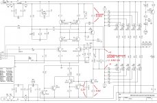
You can download 200.7 schematic which amp circuit should be close to your model just your model using 2 pairs mosfet output. B&K basic power amp circuit almost the same from low to high model, just using higher supply voltage and more output transistors for high power amp.
BK Components Reference 200.7 - Manual - 7-Channel Power Amplifier - HiFi Engine
If you tested all the pre-drivers, resistors, diodes and caps are good and in spec, for a test way, you can put the new driver transistors and only a pair of spare(unmatched) mosfet to the amp to test if it can work normal, or you just put the new transistors and mosfet together and test it.
Please make sure all the resistors around the driver and mosfet ouput are ok and add the zobel networks to all outputs post if there is no installation.
Next time if you found your amp something wrong, don't turn on with speaker connected, disconnect speaker first to do the further test.
You can download 200.7 schematic which amp circuit should be close to your model just your model using 2 pairs mosfet output. B&K basic power amp circuit almost the same from low to high model, just using higher supply voltage and more output transistors for high power amp.
BK Components Reference 200.7 - Manual - 7-Channel Power Amplifier - HiFi Engine
If you tested all the pre-drivers, resistors, diodes and caps are good and in spec, for a test way, you can put the new driver transistors and only a pair of spare(unmatched) mosfet to the amp to test if it can work normal, or you just put the new transistors and mosfet together and test it.
Please make sure all the resistors around the driver and mosfet ouput are ok and add the zobel networks to all outputs post if there is no installation.
Attachments

Thanks - I will retest everything you suggest and see about the zobel. Thanks for the schematic not sure how I missed that one online.
No problem. I hope you can fix it.
Your amp PCB can put 3 pair output mosfets per channel, you may consider to mod the center channels to give you a more powerful amp
Your amp PCB can put 3 pair output mosfets per channel, you may consider to mod the center channels to give you a more powerful amp
The only strange part is it has +/-65V (red/black) going to the 4 channel board, and also has +/-65V (Red/Orange/Black) along with Ground (Green). Not sure why it needs two wires carrying the same rail voltage, but I think it is a mute circuit possibly, testing if there is full rail voltage (guessing though).
Based on the schematic it looks like they set up the amp front end to be CRC filtered and unfused, thus the reason for the two separate DC bus wires.
OK - I tested the outputs and drivers again (replaced the drivers with new ones, with similar Hfe (124 & 129). I also re-checked all the pre-driver transistors still on the board, both for shorts with the DMM, but also related to the three other working channels as a comparison (all checked out good). I also checked more than half the resistors again, comparing to a good channel - all measured good?
The amp powers on (I brought it up with a DBT at 60w, 150w and then w/o bulb) - I can set the bias (currently set low at 20mV). Everything seems to be working, but I'm getting +65Vdc on the speaker terminals. Bias and voltage on speakers is stable, but I only had it on for 5 mins., wanted to see if I could get some help before I caused more damage.
Any idea what these symptoms point to as the problems?
Amatuer, but leads me think one pair of the outputs are actually bad? Noob theory - does the +65Vdc point to 2SJ162 (negative rail) side of outputs? Or better yet, does it point to a pre-driver transistor on the negative rail? I have spares and they are easy to change, should I pull and test all of them again?
I'm at a loss at this point! Thanks for the suggestions up to here.
If you put back new drivers and mosfet, power on with no burning parts or fuses but showing output one supply rail voltage, then it maybe caused by bad solder joint, joined solder points or a broken PCB copper trace, If all parts are ok.
Please investigate the PCB solder joints and copper traces special on the negative supply driver side 2n3440.
Please investigate the PCB solder joints and copper traces special on the negative supply driver side 2n3440.
the diagram with some voltage values for the drivers for reference, measuring voltage values close to the diagram is ok.
Attachments
Last edited:
Thanks for the voltages.
I replaced all the outputs, re-tested the old drivers (tested good, both DMM and tester) so i put the originals back in. Rechecked all the pre-drivers in the board, all checked out okay.
I can set bias and play music BUT the bias is very touchy and if I go much over 35mV, it immediately goes to 100mV+ seen it as high as 183mV before I could get the pot turned down. When I turn it down, it immediately drops to 10-15mV and takes a full turn or more just to get back to 20mV?
I guess my next step will be to take it apart again and actually pull all the pre-drivers and see if any test bad out of circuit?
I have not added the zobel yet, was going to add to an external speaker protection box I am planning to build before putting this back in service. So speaker out to protection box (zobel on the speaker posts), then to protection board and out to speaker posts, these will be connected to speaker wires going to speakers. Will this work? If not, I will have to tear-down the amp much further, to get access to the back panel to install.
It's painful for me to repair amp board with a double side PCB, desolder the through-hole parts without broken the PCB through-hole connection is a tough job. If the through-hole connection broken, it may cause a open circuit on one side, so that we must double check the connection on both side after a new part replacement.
For the bias problem, please test the VR if it's value change linear when tuning. Maybe need a new replacement.
It's good to add an external speaker protection circuit for the amp, I think the zobel add to the protection box will be ok, it just added for safety, the original amp can work without it.
Ok, I will try a new pot first and just recheck the drivers again in circuit (maybe I missed something) Any issue going to a 1k instead of a 500r? I have a known good Bournes 1k.
Small update - no progress, but put together an order and should be here Friday afternoon. Got some resistors, capacitors, new drivers and pot (in case the ones from China were fake), also got new power connectors, the locking clips all broke when I took it apart the first time.
My plan - take my time and re-test everything one last time, resistors, diodes and transistors and replace the drivers and pot (with new Mouser parts) and any other items that test out of spec. I may go ahead and take out the pre-drivers again and test out of circuit - there must be one in that bias circuit that has a on-off-on fault of some kind.
Also may need to verify the schematic (will take a long time, as I'm very new to tracing circuits), as I'm already sure the transistor numbering does not match my board - which is a bummer.
Any input on what transistors to focus on, to get the bias to become more stable? Appreciate all the assistance so far.
Update -
It's ALIVE!!! It was indeed the pot, however I am taking it very slowly and re-tested all transistors and resistors and everything checked out.
Powered with the DBT at 60W and then 150W, see bias to 25mV and let it cook for 30 mins. Then I played some very low music - and it played fine.
Then I took the DBT out of the mix and set the bias to 30mV and again let it cook for 30 mins. more and played some music off and on at low volumes.
Question - how do you test a repaired channel to feel comfortable that everything is working and as it should be? I am waiting for the caps to discharge, then I will add in the other 3-channels of the amp and let it run for a good 1-2 hours to make sure the bias is steady. Then I plan to take a look at this repaired channel on a scope and make sure the input and output is the same (or very close) and that it goes into clipping without any oscillations or issues (does so cleanly).
What other tests should I run (would you run) - I want this to be back in my HT and never have to worry about it again, so I'm going to really test it before doing that.
Good news! The amp is working.
I think you already did the best to test the amp with scope and with 1-2 hrs trial run.
When you added the external speaker protection box to your amp, everything will ok.
I think you already did the best to test the amp with scope and with 1-2 hrs trial run.
When you added the external speaker protection box to your amp, everything will ok.
I haven’t added the protection box yet - it’s been delayed, it was an overseas purchase two weeks ago.
Will not be putting into service until I have protection connected and working properly.
Any reason XLR and RCA wouldn’t both be stable? I am testing with RCAs but plan to use XLR in my HT?
Thanks for all your help and highlights on the schematic-really helped me know exactly what to test and verify.
Don't mention it, I'm glad to help.
I think both XLR and RCA input designed to be stable, or you can test it again before putting into service.
I think both XLR and RCA input designed to be stable, or you can test it again before putting into service.
- Home
- Amplifiers
- Solid State
- Issue with B&K Reference 125.7