What DF96 said. You have three LF roll-offs (zeros) in this circuit, the cathode bypass, the OPT, and the coupling caps. Additionally, the power supply impedance rises at very low frequencies and you have two time constants associated with that, as well. I would guess that your problem is right there.
First step is to stiffen the power supply. If you're not allergic to regulators, this is one of the best improvements you could implement. At the very least, regulate the input/driver stage circuitry, while increasing the capacitance at the output stage feed; 100-200u is a reasonable first try, and will not result in too much bulk or expense. My personal choice for driver stages is a simplified Maida regulator (I showed schematics and design equations in my Red Light District and ImPasse articles on my website), but there are lots of other good choices as well. No need to get too fancy, even a simple Zener referenced emitter (or source) follower will be a massive improvement.
99% of the time, making the power supply rock solid will sink the motorboat.
Reducing the coupling caps as DF96 suggests will move that roll-off up, increasing stability and fixing the problem, but also increasing LF distortion because of reduced open loop gain. So the other approach (assuming the power supply has been sorted) is increasing them. The downside to that is increased recovery time after overload. Pick your poison.
Thanks for all suggestions so far. I will have to try each after the other.
Wow I just moved feedback from 8 ohm taps (speaker plus) to the free 16 ohm taps and right channel gave out its war-cry. I guess I have a phase shift somewhere and feedback went positive. I think I might be root cause on tracks.
The two OPTs are different series and different colourcodes on cables so its hard to really know which are which on the two.
Now I have to tinker. Hmm should I try to figure out relating OPT wires or just put in another pair of Edcors with matching colourcodings...
Or could I now just shift the two taps I am using for plus and minus out and I'm home?
Or could I now just shift the two taps I am using for plus and minus out and I'm home?
Edit. Just tried, didnt work, same result. My son is now mad at me😀 Stop screeching dad😀
I just skimmed this thread and didn't see the recomendation of checking to be sure you are applying GNFB and not GPFB.
Check to make sure the connection of feedback REDUCES the gain. If the gain increases with the application of feedback, you have accidently applied positive feedback instead of negative feedback. If this is the case, swapping grid drives to the output tubes to correct this.
Gotta take GrandSon to a ball game. TTFN
Thanks Gimp. I just went over wiring on the output tubbies to make sure its consistent. Measured so all G2s have small (40ish) DCR and all anode large DCR (200 ish) from OPTs primarys and they have. They follow colours on primarys but not on secondarys. I didnt have time to check consitancies from input tubes, I am also out with kiddo now.
I guess one scope probe over primarys (anode-anode) and other probe over a dummy on secondarys will tell me if phase is consistent over OPTs. Then the same over phase splitters. Im not really sure how to measure this best way, tips and tricks are welcome!
Have fun at the ballgame!
Staffan
I guess one scope probe over primarys (anode-anode) and other probe over a dummy on secondarys will tell me if phase is consistent over OPTs. Then the same over phase splitters. Im not really sure how to measure this best way, tips and tricks are welcome!
Have fun at the ballgame!
Staffan
Last edited:
Looking at the power Tx,
ER....Its not a good idea to have single cables through holes on AC supplies..
The two AC cables for each supply should come through the same hole..
I guess (two grey) two green (two black)<<each supply? (you can just cut a slot across each pair of holes to overcome this)
Whats the chassis made of?
I also don't see any isolation for the transformer mounting pins...I guess you have a shorted turn on the Iron??? (Not the windings the mountings)
Easy to check there should be no connection between each of the four mounting screws and Tx iron..with a meter set to ohms.
ie no connection across the laminations to the screws so you dont get a loop via the screws and the laminations. (shorted turn)
Does the incomming mains have a grommet (through the chassis)?
Keep Feedback and output wiring away from inputs..check phasing of feedback..
Regards
M. Gregg
Thanks for feedback, sorry I was in a hurry and didnt have time to anwer correctly.
Holes: you say twisted main/return per hole right?
Tx: it has a bias winding to that I dont use. Not sure of colourss now but its mains, HT secondarys, bias and filament windings going up and down.
Chassie: painted steel
Incoming mains: normal male EIC
I will check the Tx condition later. First now is to make sure FB is neg and phases are correct.
About Tx mounting. Are you saying I should isolate core from chassie?
Thanks!
Staffan
Last edited:
What DF96 said. You have three LF roll-offs (zeros) in this circuit, the cathode bypass, the OPT, and the coupling caps. Additionally, the power supply impedance rises at very low frequencies and you have two time constants associated with that, as well. I would guess that your problem is right there.
First step is to stiffen the power supply. If you're not allergic to regulators, this is one of the best improvements you could implement. At the very least, regulate the input/driver stage circuitry, while increasing the capacitance at the output stage feed; 100-200u is a reasonable first try, and will not result in too much bulk or expense. My personal choice for driver stages is a simplified Maida regulator (I showed schematics and design equations in my Red Light District and ImPasse articles on my website), but there are lots of other good choices as well. No need to get too fancy, even a simple Zener referenced emitter (or source) follower will be a massive improvement.
99% of the time, making the power supply rock solid will sink the motorboat.
Reducing the coupling caps as DF96 suggests will move that roll-off up, increasing stability and fixing the problem, but also increasing LF distortion because of reduced open loop gain. So the other approach (assuming the power supply has been sorted) is increasing them. The downside to that is increased recovery time after overload. Pick your poison.
SY. Thanks for taking your time! Your RLD is waiting to build, if I wait any longer maybe the parts are crawling together by them selves. Still looking for a small secondary tranny, my winders wouldnt get in touch with 0,1 mm secondarys so I guess I have to go with a larger EI.
I find this Hafler schema to be one of the fair sounding, few components, regular components, cheap components circuit on the market along with some other here on this site so my aim was to learn something from it and maybe write a little begginners guide from my findings.
Ofc it would help my curage if I get it to work properly before I start posting do's and don'ts. First build before I got regular stock buyable stuff was with salvaged stuff. I have proper Antec, Edcor stuff etc laying for making something for an average builder to try with, but I would like this one to work first.
The thought is to maybe develop it further with modern chisel help etc, but I think its educational, both for me and others, to know that you can actually build fairly decent stuff with just ol' caps, resistors and tubbies that work fairly well. And easyer to understand also.
That is, if I will get the stuff working ofc😀. Im sure I will, with your good help😉
Cya. /Staffan
Staffan,
There are a lot of good ideas being thrown at you especially as regards power-supply performance. But the first step in troubleshooting is to try to isolate the problem before applying a solution.
Two possibilities have emerged in this thread-discussion: 1) the power supply regulation is poor, and 2) there is something wrong with the amplifier circuit itself (such as feedback, feedforward coupling capacitors, etc).
Normally, we try to take the easiest things first and save the major circuit reworks for later when stars go dark, volcanoes erupt, and hot-rocks are falling from the sky. (or, even more important, we want to enjoy the music and spend time with the family!)
In this particular case, the first step is to try to isolate a power-supply problem vs. amplifier topology/parts problem.
If you have a good, clean, regulated HV lab supply handy that you can use to test your amplifier, then you are very lucky! Just dial up the correct voltage, substitute it for the built-supply in your amp, and see what happens to the motorboating.
If, like most of us, you do not have a good HV bench supply then it might be easier to assume (for the moment) that the power supply in your amplifier is adequate and try something easier.
In troubleshooting any feedback-amplifier topology, the first thing to do when you have a suspected oscillation is remove the feedback. Feedback is used, typically, to flatten the gain/frequency response of an amplifier, but for the purpose of this test the open-loop gain should be fine.
You already reduced the feedback when you increased that 1k feedback resistor to 2.4k, but it is better to be sure before moving on.
Normally, you would just unsolder the feedback wire at the point where feedback is inserted - in this case, the cathode of your 12AX7.
However, this topology uses the feedback resistor as the cathode bias resistor - a clever attempt by the manufacturer to save a few pennies (kroner? 🙂). Not a problem, though, if you a) disconnect the feedback and b) tack a temporary 1k resistor from cathode to ground right at the 12AX7.
Then fire up your amplifier and see if the "motorboating" is still there, changed in nature, louder, quieter, etc.
If it is absolutely, 100% gone then your problem is in the feedback and you can proceed with the suggestions of fiddling with the bypass/coupling capacitors that SY, DF96, and others have presented above.
If the problem is in the power supply, then the motorboating will very likely still be there - the global feedback (OPT to 12AX7 through the 1k) is unlikely to be interacting with the power supply to cause the motorboating.
If it is none of the above - then we will just have to find another place to prospect 🙂
Good hunting! 😎
Sam
BTW - This is all presented in the spirit of learning. If some of these lessons are already learned, then perhaps others reading through this discussion-thread can use them. It is a matter of going through a design in a step-by-step fashion to find a problem. In my experience, the blind application of tricks and shortcuts is a poor substitute for real troubleshooting.
Been there, done that...
Systematic troubleshooting of any new design or any repair-job will save you a LOT of headaches and time.
It might seem slower while you are doing it, but isolating a problem and THEN applying a solution is always, always, always the fastest path to a final product.
I can offer a cup of coffe and a HV lab supply 😀.
A handfull of 3legged HV regulators can change owner if you bring cake !
A handfull of 3legged HV regulators can change owner if you bring cake !
Schwartzwald, Boston, Budapest, cheesecake, strawberry, lime. Ill take the morning train if just Dortmund kicks a goal now. Otherwise the 9.30 earliest
Stajo,
You must not put a single AC cable though a steel chassis...you must take two cables, supply and return through one hole..
The Bolts that go through the transformer must not connect to the laminations (be in contact) you must insulate the mounting bolts from the laminations..try using a flat washer with a fibre washer under the flat washer to insulate it. So think like this..you must not have both ends of the mounting screws connected to metal.
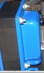
If you look at this picture of an Edcor Tx, under the nuts there are plastic insulator / inserts..the mounting bolts must be insulated at least on one end from the Transformer laminations.
Regards
M. Gregg
You must not put a single AC cable though a steel chassis...you must take two cables, supply and return through one hole..
The Bolts that go through the transformer must not connect to the laminations (be in contact) you must insulate the mounting bolts from the laminations..try using a flat washer with a fibre washer under the flat washer to insulate it. So think like this..you must not have both ends of the mounting screws connected to metal.
If you look at this picture of an Edcor Tx, under the nuts there are plastic insulator / inserts..the mounting bolts must be insulated at least on one end from the Transformer laminations.
Regards
M. Gregg
Attachments
No hurry !
Coffee is available 24/7 🙂.
I have a very upset wife for the moment.....
I´m redecorating the workshop using here kitchen table as workbench 😀.
The stack of very old HP instruments was making the shelf sag about 1" so it´s now being reinforced by 2x3"
Coffee is available 24/7 🙂.
I have a very upset wife for the moment.....
I´m redecorating the workshop using here kitchen table as workbench 😀.
The stack of very old HP instruments was making the shelf sag about 1" so it´s now being reinforced by 2x3"
No hurry !
Coffee is available 24/7 🙂.
I have a very upset wife for the moment.....
I´m redecorating the workshop using here kitchen table as workbench 😀.
The stack of very old HP instruments was making the shelf sag about 1" so it´s now being reinforced by 2x3"
😀...
 <<<<
<<<< <<<<
<<<< ...Low WAF...
Regards
M. Gregg
Staffan,
Two possibilities have emerged in this thread-discussion: 1) the power supply regulation is poor, and 2) there is something wrong with the amplifier circuit itself (such as feedback, feedforward coupling capacitors, etc).
I am very greatful to all this suggestions and it will help me to reconstruct it.
Though my intuition says that Mr Hafler was not wiggeling on his bike. I am sure that regulated feed can affect the circuit in some kind, to better or worse.
I have tried it and it made a difference. Atm the splitters are fed by a 15 H dual 47uF, I tried the original circuit to with the values suggested but on 99 dB speakers it playes like a goddess but I just cant live with the hum. It goes away either by balancing the output tubes to the max or adding more u on second C. The first is prefered soundwise, second is just a makeup on a stiff. Sometimes i think of regulators like this to. Live Music comes from live wires.
Tomorrow I will dig in to phase matching hopefully. I hope for all your DIY powers to help me.
Cheers
Staffan
Sticking my cheek out like this would normally get my balls fried. I guess neither SY or Anatoly are awake or even bothers to answer. Ok, I get back to my soldering.
Last edited:
Run 100Hz-1kHz-10kHz square waves through it. So we can have an idea. Choose DC coupling for the Tek's input configuration to avoid additional phase shift for the 100Hz square.
They gave you very solid advice as I have seen. Time for some measurements now though so we get to know more about the system.
solid advice
Well if I plug it in to the speakers I guess you can hear it to Greece. If I plug it to the maesurement equipment I'm not sure but its close. Asking me for a squarewave in this moment, I would prefere cake.
I have to find out why I have gpf instead of gnf. By measurement. I will find out dont worry. I just asked fore some help.
Last edited:

- Status
- Not open for further replies.
- Home
- Amplifiers
- Tubes / Valves
- ISO a motorboat