I do really disagree that this configuration filters RF really well. There is an awful lot of it coming out of the DAC itself. For my money the only things that filter RF effectively enough are inductors (and of course, ferrite beads).
The signals coming out of the DAC are differential. I think most noise coming out of the DAC is common mode noise. The two capacitors between the two outputs of the DAC should get rid of most common mode noise effectively.
I only worry about the last stage of the filter, i.e. the differential opamp. In the positive input the noise is shunt to the ground. In the negative input, the noise is fed into the opamp, and it relies on negative feedback to cancel the noise. At very high frequencies I am worried that phase shift and limited open loop gain may affect the result, as we are not using ideal opamps here. It looks like I should use a high bandwidth opamp here. The LM4562 with 55MHz GBW should be fine. But strangely, nobody seems to record good experience with LM4562 in this position.
I am also worried about the non linearity of ferrite beads. As for inductors, I can't see where I can use it in this particular circuit as the noise are shunt across the differential signals, not to ground. With ferrite beads, hopefully they can dissipate the RF noise as heat.
Your math looks wrong there - 3.9mA p-p gives 1.6V peak or 1.13VRMS.
Oops, I forgot to divide it by 2. Thanks for the correction.
There's a huge amount of noise - but mainly that noise is differential-mode noise. That's why the filter doesn't have any caps to deal with common-mode (they'd be to ground) - rather they're between the phases.
Sure, ferrite beads will contribute nonlinearity especially if you send too much current through them. They'd best be used filtering out HF from the rails, that is unless you fancy passive I/V in which case they could do a decent job (in long strings) getting rid of the RF riding on the audio.
<edit> Just mention here that the non-linearity which is objectionable to the ears IME comes from active parts (especially opamps) exposed to what may seem like very low levels of RF. In comparison, inductor and bead non-linearity is subjectively benign.
Last edited:
I was confused. I thought of it, you are right, the caps between the signals are there to deal with differential noise, not common mode noise.
If there was much common mode noise, a common mode choke would help here.
But then, there is nothing wrong with this circuit!!!
Inductors are not going to reduce the RF noise here, they are just there to shift the noise from one place to another.
If there was much common mode noise, a common mode choke would help here.
But then, there is nothing wrong with this circuit!!!
Inductors are not going to reduce the RF noise here, they are just there to shift the noise from one place to another.
You only need to reduce the noise at the opamp inputs (and on their supply rails), so shifting it away from those sensitive places is perfectly adequate as a solution. Inductors do have losses which turn RF into heat, just as ferrite beads do.
A CM choke isn't a bad idea but would need to be prior to any active circuitry -once the RF is seen by opamps they'll down-convert it into the audio band where no filter can touch it.
A CM choke isn't a bad idea but would need to be prior to any active circuitry -once the RF is seen by opamps they'll down-convert it into the audio band where no filter can touch it.
Or the op amps might just convert some of the RF to DC or pulsating DC, possibly changing internal operating points and sounding "off" for no apparent reason, and maybe even not noticeably-enough for a user to think anything is actually wrong, which could be quite insidious.
A progress update:
I have not progressed to round 4 with opamp changes yet.
Although round 3 snubber mods to the SMPS removed all the ringings as illustrated in the drawing in post #123, I later found that the amplitudes of the voltage spikes became higher comparing to the amplitudes before putting on the snubbers, especially on the -12V rail. So there were a bit more work to be done. After changing the snubber values a couple of times, the amplitudes came down a bit. Through this process I have now learnt some new tricks and I think I can now determine the snubber values accurately. I am confident that once the new parts are ordered and arrived, I will get the job done properly.
I used to use mainly formulas and sometimes LTSpice transient analysis to come up with the snubber values. I now found that using LTSpice AC analysis I can get even better results, as last time I missed some values and this time I matched everything, including Marantz' values, very well.
I have found some 25V 22uF X7R ceramic capacitors in Digikey. I believe they should work very well on the rails immediately after the rectifier diodes on the secondaries. Ceramic caps of smaller values like 0.1uF will only work above MHz region, and they create large impedance peaks in the low MHz region, so they cause more problems than they are intended to solve. I think I can only avoid creating impedance peaks (the thing that makes the voltage amplitudes higher) by using values above 10uF. For 22uF ceramic they work in the low hunderd kHz region as well. I have very high hope that they will quiet down the rail spikes and make significant improvements, as we cannot expect electrolytic capacitors to work above a few hundred kHz.
It would be great if these 22uF ceramic caps could be put on the digital rails of 5V and 3.3V supplies. But I suspect that they will most likely cause instability of the regulators. What a pity!
hi-k ceramic have big V coefficient - use near rated V and you may lose >50%
stacked metallized film comes in PPS or PEN for smt
stacked metallized film comes in PPS or PEN for smt
Last edited:
Those 22uF X5R have +/-20%, so if they lose 20% they still have 17uF, which is still excellent. In the worst case, I can parallel 2 to get 34uF.
I will explore PPS in SMD. I found Leaded PPS has fairly high inductance. I have bought many 1uF MKP but found out they have 70nH inductance. I hope PPS in SMD is a lot better.
I will explore PPS in SMD. I found Leaded PPS has fairly high inductance. I have bought many 1uF MKP but found out they have 70nH inductance. I hope PPS in SMD is a lot better.
Yes - in many cases much more than 50%. The voltage coefficient seems to depend on manufacturer, I have found TDK and Samsung amongst the best, Murata I tend to avoid. Its not uncommon to go down to 10% of the specified value when biassed at the rated voltage for an X5R. Don't even mention Y5V.
TDK's capacitor selector web page is very useful - it allows you to search based on the capacitance you need at the rated bias voltage.
Search by Characteristic | Multilayer Ceramic Chip Capacitors | TDK GLOBAL
@HiFiN - when you say 'these caps have +/- 20%' you're talking about the capacitance tolerance at zero bias. As jcx says you will lose a lot more than 20% if you take the bias up to 25V/ Depending on the package size you have, your 22uF might well only be 10uF at 5V bias.
Last edited:
Thank you so much, guys.
I was only looking at T coefficiency at 0 bias and did not think of the voltage coefficiency.
O.K. Let me buy the X7R instead of X5R by paying a bit extra. It looks like I can never save money on parts.
I was thinking about using 25V 22uF X7R on 12-15V rails, and using 16V 33uF X7R for the 5V rails. How much capacitance will I get? The datasheet doesn't tell anything about the voltage coefficiency.
By the way, I am not using SMD because the existing PCB would not allow it. I am using leaded ceramic capacitors while cutting the leg lengths to about 2mm.
Who says size does not matter? For ceramic caps these leaded caps are larger than the SMD caps, so hopefully the voltage coefficiency is better.
Who says size does not matter? For ceramic caps these leaded caps are larger than the SMD caps, so hopefully the voltage coefficiency is better.
Last edited:
O.K. Let me buy the X7R instead of X5R by paying a bit extra. It looks like I can never save money on parts.
As far as I'm aware, they're pretty much the same when it comes to voltage coefficient. X7R just allows operation over a wider temperature range. I reckon its OK to stick with X5R. To get more capacitance at bias you'd need to go up in package size - if you're currently at 1206 then go to 1210 for example. But from my poring over cap datasheets and price catalogues, above 1206 takes the price up rather steeply. Generally better (i.e. more cost-effective) to parallel 1206s.
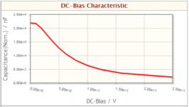
How much you get depends on your vendor. Do you have TDK (generally the best), and is this a 1206? In which case the curve looks like this (22uF X5R). Going up in nominal value doesn't always get you more capacitance under bias so I'd recommend against 33uFs, but you can check them out yourself on TDK's site which I linked in my earlier post.I was thinking about using 25V 22uF X7R on 12-15V rails, and using 16V 33uF X7R for the 5V rails. How much capacitance will I get? The datasheet doesn't tell anything about the voltage coefficiency.
<edit> Ah now I see you're using leaded types, all bets are off. I have no experience of them.
Attachments
Last edited:
Given that they are of size of L:7.5mm W:4mm H:8mm, they are a lot bulkier than the SMD types. Given that SMD capacitance increases with size, I guess they should have higher capacitance than the SMD types. The drawback is of course higher inductance. I think I may parallel 2 of them at least, and may be 4 if space is allowed.
I have just simulated it. If the 22uF drops down to 5uF, there is no impedance peak. If it gets down to 2uF, it will make the rails 2dB worse at 500kHz. So provided that it does not get worse than 2uF, it may well be acceptable. They will cover very nicely above 1MHz up to tens of MHz, where electrolytic capacitors are merely resistive and slightly inductive in the region.
I have just simulated it. If the 22uF drops down to 5uF, there is no impedance peak. If it gets down to 2uF, it will make the rails 2dB worse at 500kHz. So provided that it does not get worse than 2uF, it may well be acceptable. They will cover very nicely above 1MHz up to tens of MHz, where electrolytic capacitors are merely resistive and slightly inductive in the region.
You could have a try with LT1355 (which I've not tried myself) or HA-5222 (which I have and quite like, as opamps go). The latter one might be a bit hard to find though. For JFET inputs you could go for AD8066 - to my ears its a bit coloured but not objectionably so.
Thanks for the recommendation. I am now interested in AD8066 I think I will order them for the filter stage. I think I have wasted the money on the LM4562 as I have already bought them.
Will you bypass across the supply pins of the AD8066, just like LM6172?
I've only used the AD8065, the single version of this one, but yes, I'll decouple between the two supply pins. Nowadays I have mostly gone away from dual (balanced) supplies with opamps - running them referenced to the -ve rail gives advantages in PSRR (-ve rail PSRR on most opamps sucks worse than +ve rail) and often CMRR. I'll tend to use them balanced too as this makes better utilisation of the power supply and gives improved dynamic range over SE.
One question to ask.
For the I/V opamp, I assume there is no filter effect because of the 820R and whatever capacitor across it.
In other words, I assume that the output from the DAC chip has a 0 impedance. Any resistance here seems to make the I/V opamp stage a filter and the filter response changes dramatically along with the output impedance change.
I had the impression from most of the I/V circuits I saw that a DAC output had indefinite impedance, or at least very high impedance. I don't remember anything in these circuits that would have altered the response. Still, I haven't actually seen someone come out and say exactly why DAC chips get this strange treatment. Granted, I haven't looked for the answer yet.
- Status
- Not open for further replies.
- Home
- Amplifiers
- Power Supplies
- Is this real? - simulation of parasitics