Abraxalito,
Are you in Hangzhou now? That is really a nice place at this time of the year. They said Suzhou was the manufacturer of Chinese beauties in the old days, but I reckon it is Hangzhou.
For me I find beauties mostly in music, not much elsewhere these days. I am getting old.
Bill
Are you in Hangzhou now? That is really a nice place at this time of the year. They said Suzhou was the manufacturer of Chinese beauties in the old days, but I reckon it is Hangzhou.
For me I find beauties mostly in music, not much elsewhere these days. I am getting old.
Bill
Last edited:
The leakage capacitance to socket ground forms a series resonator with the ground loop inductance, so at that frequency there is as close to an infinite current sink as you can get. This is one caveat with isolated systems. To damp this resonance the most direct way would increase leakage by 5 times.
Unless you break all the ground loops cause by the chassis connection, your hands are pretty much tied.
Unless you break all the ground loops cause by the chassis connection, your hands are pretty much tied.
A while ago, I installed a "switch" to connect and disconnect the earth wire in the IEC socket. The difference is audible.
I later tried connecting to the earth via a 30A diode bridge but then realised that the capacitance of the bridge is so high it simply defeats the purpose.
So I no long connect the equipments to earth. If we analyse how it can cause life risk, that risk is so small. The chance of getting hit by a car on the road may be 1000 times higher.
Are you in Hangzhou now? That is really a nice place at this time of the year.
Yep, very much still in Hangzhou. But unless you're a heat junkie I'm not going to recommend it right now - we've been having a string of days where the max has been 40oC. Barely a cloud in the sky except when they seed them with rockets. Humidity though hasn't been devastating but still energy-sapping. If you're planning a visit best wait a month or more - the osmanthus comes out at the end of Sept. Yes still plenty of beauties here 😀
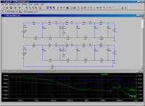
I have just analysed the Marantz SMPS board more carefully, and I can't believe how things could have done this way. As I mentioned earlier, all of +/-12VA, +12VM, +5V and +5Vstandby have ground connections joined at the output socket of the board sitting on a ground plane. So the best outcome of onboard LC filtering cannot be better than a first order low pass filter, as implied by the initial simulation result I posted. Marantz actually attempted second order filter, but I don't think it works with such a way of grounding.
I am attaching a simulation of a ladder style grounding of passive LCR filtering (top circuit, green curve) comparing to Marantz style grounding (bottom circuit, blue curve). What a difference!
No wonder I could plug in Keatoken's KM as the pre-reg and boost up PSU filtering on Marantz reference series SA11S1 then achieve very good result! Marantz PSU filtering is insufficient due to its deficiency in grounding.
I was initially planning to replace the onboard first order LC low pass filters with small boards of 2nd or 3rd order LC low pass filters but with Marantz way of grounding this is not going to achieve any positive result. It could make things worse.
I think the only way I can overcome this problem is to disconnect the SMPS ground from the chassis, and install the extra LC filtering AFTER the output of the SMPS board, not on the SMPS board.
Attachments
Yep, very much still in Hangzhou. But unless you're a heat junkie I'm not going to recommend it right now - we've been having a string of days where the max has been 40oC. Barely a cloud in the sky except when they seed them with rockets. Humidity though hasn't been devastating but still energy-sapping. If you're planning a visit best wait a month or more - the osmanthus comes out at the end of Sept. Yes still plenty of beauties here 😀
I was there twice - nearly 30 years ago. It was like paradise, Garden of Eden, pure magic. No traffic, few tourists, no skyline buildings, beautiful West Lake... I can't think of how it looks now. I will go there for a visit one day. But that is out of the topic.
What is the name of the type of the connector and socket used in that 4 wire power supply connection?
I searched the Digikey catelogue for connectors and cables, and it returned thousands of them of hundreds of types.
I need to buy two exactly the same female sockets, and one cable with both plugs male, so that I can introduce a small passive filter board in between the SMPS board and the DAC board.
Attachments
gootee,
You are a champion! Thanks. 🙂
That is what I need. I am familiar with analogue LCR filtering but not digital LCR filtering.
Regards,
Bill
Here is a progress update.
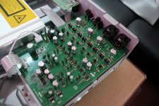
I studied the board more carefully and finally found a way to achieve 2nd order filtering on the 12V outputs. This required at a minimum of cutting one track and drilling 3 new holes and re-routing some of the connections. Theoretically these should help achieve better results as simulated above.
I replaced the SMPS input bridge rectifier from garden variety diodes to UF5408. The input cap was changed to Rubycon TXW 150uF 450V. This series is made for SMPS. This is the only capacitor I increased the value (from 100uF to 150uF). All other onboard electrolytic capacitors have been changed to either Panasonic FR, FM or Rubycon ZL of the same values. In addition, the 3 x +/-12V outputs have been rewired to use 3 separate small boards mounted vertically to implement a 2nd order LP filter. I was careful not to introduce much additional capacitance, so the extra LCR LP filter is set at high frequency just under 50kHz. The Marantz SMPS switches either at 60kHz or 100kHz (from the controller datasheet).
When I connected the upgraded circuit board, it did not work. It was a failure. The circuit board was no longer functioning. I could see the 5VSTB dropping down when turned on, and other outputs did not have voltages, obviously caused by the controller shut down.
It took me a few more days to study the SMPS circuits more carefully and eventually tracked down the problem - a TO-92 LM431 shunt regulator was burned out shorted.
How could it be damaged? I don't have the answer. Was it due to too much drilling and handling of the board? static electric charge? Oscilliation caused by low ESR capacitors? Instability caused by extra 2nd order LP filter which altered the regulator gain loop?
I pulled out my 2nd order filter components but still used the low ESL/ESR caps. I replaced the LM431. It worked! I was happy, as this was the first time I worked on and repaired a SMPS.
I then installed a 20MHz ferrite bead and a 1GHz ferrite bead in series with the analogue +/-12V supply. No problem this time.
******
It was a big surprise that the image quality of the blu ray player was markedly improved. I thought the image may improve but never expected the improvement to be so big. When I first bought the player, after run-in, I really disliked the noisy pictures. The cheap Sony S580 ($220) and the top of the range Sony S780 (multi-region) produce much better picture than this Marantz UD7007. Now for a big surprise, the noise is substantially reduced. It now betters the Sony S780! I have a fairly large 65 inch LED TV so noise is easily visible. I watch ballets a lot these days. Now I can see the fine movements of the dancers better and it gives me new sensation at a new level of experience! Skin tone, colour, texture, details, everything has been improved. Only for this, it was worth the upgrade.
As far as audio is concerned, as posted earlier I upgraded the analogue board and got rid of 70% harshness in the treble. I was hoping the PSU upgrade would get rid of the remaining 30% harshness.
The upgrade of the PSU board did not go as far as what I originally anticipated, as the 2nd order filters were not installed. But the upgraded component quality as well as the 2 new ferrite beads did change the sound.
Better or worse? I am not sure. The ferrite beads seem to work well. At the upper end of the harmonics the player is now better. I previously heard much exaggerated triangle and symbals and now they sound pretty fine. However, I suspect that the impedance peaks on the power supply have been shifted down from higher frequencies to frequencies within the audioband. I think that the upper mid range now sounds a bit harsher.
The next thing to do is to measure it. I will see if I can spare some time tonight.
Last edited:
Great report. And good progress.
Are you going to make another attempt at using the 2nd-order filter boards, or maybe try one of them or something? Or can you test them as stand-alones?
How did you use the ferrite beads? Just one pass through them, or any wraps? And where are they, exactly? Did you try adding more?
Are you going to make another attempt at using the 2nd-order filter boards, or maybe try one of them or something? Or can you test them as stand-alones?
How did you use the ferrite beads? Just one pass through them, or any wraps? And where are they, exactly? Did you try adding more?
I shake my head that people can accept this assessment of what improvements may occur in, in this case, the visual sphere - yet mention similar sorts of gains made in an auditory sense, and the roars of anger from the 'objectivists', demanding DBTs, etc, is deafening ... 🙄It was a big surprise that the image quality of the blu ray player was markedly improved. I thought the image may improve but never expected the improvement to be so big. When I first bought the player, after run-in, I really disliked the noisy pictures. The cheap Sony S580 ($220) and the top of the range Sony S780 (multi-region) produce much better picture than this Marantz UD7007. Now for a big surprise, the noise is substantially reduced. It now betters the Sony S780! I have a fairly large 65 inch LED TV so noise is easily visible. I watch ballets a lot these days. Now I can see the fine movements of the dancers better and it gives me new sensation at a new level of experience! Skin tone, colour, texture, details, everything has been improved. Only for this, it was worth the upgrade.
Ahhh, well ... 😎
Great report. And good progress.
Are you going to make another attempt at using the 2nd-order filter boards, or maybe try one of them or something? Or can you test them as stand-alones?
How did you use the ferrite beads? Just one pass through them, or any wraps? And where are they, exactly? Did you try adding more?
The ferrite beads are put in series with the output inductor or wire, which goes to the output socket where there is a 0.01uF SMD cap, then the socket for the connector to wire to the analogue board. The part numbers have been given in one of the previous posts.
Yes, I am tempted to try the 2nd order filter again. But at this stage, I will first see how the rails look on my two scopes. Before the upgarde, there were no tests points on the PCB for me to measure them. Now I can. I have an analogue scope that runs to 10MHz. I have a cheap digital scope that runs to 100MHz.
I have just measured the analogue +/-12V supplies with my two scopes. The ripples are pretty bad. I can see the obvious switching frequency noise at the magnitude of up to 40mV peak to peak, but it appears to have multiple frequency noise all over the places. Although one of my scopes is specd to 100MHz, I don't have high frequency probes, short leads, etc, so I can't trust the result. Nevertheless, I can't see much noise in the upper tens of MHz region. Perhaps the ferrite beads work well, or probably my scopes aren't good enough.
The measurement points are before the final +/-9V regulators. But what can these LM7809 type regulators do to noise above 100kHz? probably not by much. I don't have the test points after the +/9V regulators, but I imagine that the rails won't be very quiet.
I think my ears told me the same thing. I said yesterday I was not sure if the sound was better or not, and possibly better in the upper treble and worse in the higher midrange or lower treble.
I am struggling if I would try putting on more HF filtering for a second time, or simply build a linear regulator for the +/-12V analgoue supplies. With only 0.1A current requirement, that is very easy. The only trouble with that is I cannot integrate it into standby, etc, and can only switch the player on and off using the external wall switch.
Why would they choose SMPS for audio in the first place? If they choose it, they should implement it properly! I don't think Marantz have designed this SMPS. They probably purchased an on-the-shelf SMPS or herhapse then customised it.
Last edited:
I re-installed my 2nd order LP filters last night and guess what, the machine did not die.
The simulations I have with the way I lay out the circuit (after cutting tracks, drilling, rewiring, etc) indicate that there should be at least 60dB (1000 times) improvement at 1MHz.
Subjective evaluation found a significant sound quality improvement. Distortions seem to reduce significantly. Now the sound quality should clearly be better than a mid price dedicated CD player. However, it is not perfect. For a truly first class player, the background need to be a bit darker, and the music a bit smoother.
From the graphs shown on the scopes, the SMPS must have multiple resonances at various degrees. Why do we have a very dirty power supply then try a heavy duty filter to clean it up? It can never clean it up completely! Why can't we have a clean power supply without the need to clean it up in the first place? The more I think of it, the more I feel that using a SMPS for a line level equipment is a rather stupid idea. I mean how much more would it cost to have a linear PSU? How much extra electricity would it consume?
While the overall sound is quite good to listen to, there is one unexpected degradation - video.
I saw a dark vertical line about two inches from the right edge of the screen after I truned on the screen. This line gradually reduced its intensity over 3 hours. At the end of the 3 hours, it was not obvious any more and I had to come close to the screen to find it.
What has caused it to happen? Some resonances in the video PSU? Before I put in my 2nd order LP filters, I was a bit worried that the resonances may be caused by having too low ESR caps at the output LC, so I removed the 1000uF 25V and installed a 1000uF 16V (which has a higher ESR). I wonder if this affected the video performance. In any case, the video quality was not as good as the previous night as I found the noise was back higher.
So there is still work to be done.
By the way, I am not familliar with video circuits. Is it powered by the +12VM? or +5V? Can somebody point me in the right direction?
- Status
- Not open for further replies.
- Home
- Amplifiers
- Power Supplies
- Is this real? - simulation of parasitics