I think I will play safely and do one thing at a time. I will follow "If it is not broken don't fix it". Here is my action plan:
1) Add a couple of ferrite beads to all power supply rail outputs but don't add ferrite beads to ground wires. See if this fixes the problem (of the high frequency noise). Don't do anything more if the rail ferrite beads solve the problem.
2) Instead of having the SMPS ground directly connected to the chassis (two ground paths to the analogue board), connect the SMPS ground to the chassis via a couple of ferrite beads. Don't do more if this fixes the problem.
3) Try insulate the SMPS ground from the chassis. This breaks up one of the two ground paths from the SMPS board to the analogue board. Let the analogue board to have a single ground connection to the chassis. (This may risk generating a lot of noise due to the finite resistance of the ground wires between the SMPS board and the analogue board. I am not sure though, because all external components are connected to the analogue ground instead of the SMPS ground)
I think 1) and 2) are very low risk. They may do nothing but they will not likely do any harm.
Any more suggestions and corrections?
My suggestion is to consider CM noise, not just DM noise. From the photo you've shown, I can only see a fairly standard (non-segmented) CM choke on the mains input side. You could improve on this by fitting one with considerably lower parasitic capacitance - it would have segmented windings. You could even wind your own if you got hold of the right wire and bobbin. I've found bifilar-wound CM chokes to work well, the problem is that on the mains side you need wire with better insulation characteristics than the normal enamelled copper which isn't so easy to obtain. So you could experiment with such chokes on the DC outputs to begin with. The ferrite you were wondering about - that's an attempt at slugging CM noise on the output - those only tend to work at much higher frequencies than CM chokes.
<edit> If you look at the innards of some of the Oppo players you'll see they're using two CM chokes in series. That's another option you could try.
<edit> If you look at the innards of some of the Oppo players you'll see they're using two CM chokes in series. That's another option you could try.
The player has already got a CM choke at the mains input.
The Linear Technology App Note I attached in the first page shows that switching spikes simply pass through regulators. It is the frequency range from 20MHz to 100MHz being a worry. At that frequency range normal chokes and capacitors are not that effective.
The Linear Technology App Note I attached in the first page shows that switching spikes simply pass through regulators. It is the frequency range from 20MHz to 100MHz being a worry. At that frequency range normal chokes and capacitors are not that effective.
As I noted in my post. My point is - it doesn't look to be a very good one. CM noise tends to not be such a problem at the higher frequencies (100MHz) simply because the loops are much larger and skin effect works fairly well to dissipate the energy.
Last edited:
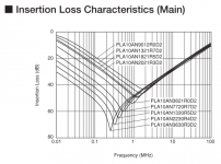
Here are two insertion loss plots of a family of CM chokes from Murata - unsegmented is to the left. The lowest current one has the lowest SRF (just over 100kHz) - indicative of plenty of parasitic capacitance. Above 1MHz there's less than 40dB attenuation. The design with 2 sections on each winding does about 10dB better above the SRF (which is also higher to begin with).
Attachments

I think the CM Choke is segmented. There are two separate sections of windings.
I can't post a picture now but you can see the pictures of an the power supply board on this page - scroll down to the middle:
Google Translate
I can't post a picture now but you can see the pictures of an the power supply board on this page - scroll down to the middle:
Google Translate
A segmented choke would have 4 separate sections (two either side) - that looks like a bog-standard one.
I think I may just buy one of those Murata CM Choke.
The one on the Marantz SMPS board is a 30mH CM Choke. I don't know the current rating though.
The one on the Marantz SMPS board is a 30mH CM Choke. I don't know the current rating though.
I know I may be turning this into another CD/Blu Ray player upgrade thread. But I guess it is still on topic because we are only discussing PSU noise filtering and grounding. Please join, stay on and share your experience. Your help is very much appreciated.
The parts I ordered from RS Components have to come from the UK and they won't arrive for another week.
Meanwhile, I have a further look at the grounding on this player in relation to connection to chassis.
On the DAC board, the analogue ground is connected to the chassis near the RCA jack. The digital ground is connected to the chassis through a binding post as well as one 0.1uF and one 0.01uF SMD capacitors. In other words, the digital ground is only connected to the chassis in high frequencies.
Interestingly, there is no direct connection between the analogue ground and the digital ground on the DAC board. The connection is made via a 2200pF polyester capacitor. Again it is only connected in high frequencies.
On the main controller board, the ground plane is connected directly to the chassis via the binding posts.
As discussed, the SMPS (flyback, isolated) PSU board has the low voltage side directly connected to the chassis via binding posts.
And for each of the power rails going out from the SMPS board, there is a ground wire going out as well.
So, there are always two ground path ways to each board because the ground current can choose the chassis connection or the wire connection.
This is messy. I mean, having two ground paths is bad, isn't it?
I think the only way to remove the double ground path is to isolate the SMPS board from the chassis. This is something I could try if it is safe.
If I isolate the SMPS board ground from the chassis, will it smoke?
I have read about that in the digital circuits, using ferrite beads or small inductors to separate each of the Vcc inputs is a good idea. Marantz do not use that. The +3.3VD supply connects to the Vcc inputs of the DAC chip as well as another logic IC's Vcc without any isolations.
Mod it or not mod it? My worry is that we can shunt the noise to the ground, but the ground is then made more dirty. So is there any gain by doing this? Perhaps the lossy ferrite beads are better.
Mod it or not mod it? My worry is that we can shunt the noise to the ground, but the ground is then made more dirty. So is there any gain by doing this? Perhaps the lossy ferrite beads are better.
Better to shunt noise to ground at an early ground, else it will be shunted into proceeding grounds anyways.
Your Marantz is double insulated, right? So no earth. Shunting noise to ground is only 'shunting' if the ground's low impedance - but with no earth, your ground is just a lump of metal floating in the air (the chassis) and hence there's nowhere for the current to be shunted to. Until you connect an earthed amp at the output RCAs, then things change.....
Let me clarify. The more PSU noise shunted through ground, the more ground noise this induced between circuit ground and PSU ground. I think this is what HiFi meant. The same PSU noise return current will flow anyways but the ground noise will be larger if the shunt points are further from the first ground point.
Your Marantz is double insulated, right? So no earth. Shunting noise to ground is only 'shunting' if the ground's low impedance - but with no earth, your ground is just a lump of metal floating in the air (the chassis) and hence there's nowhere for the current to be shunted to. Until you connect an earthed amp at the output RCAs, then things change.....
Theorectically the earth is assumed to be an infinte current sink and if that were the case you are right.
But the earth goes through dozens of metres of length of copper wires before reaching the house earth rod, so I can't see how it can work as an infinite current sink.
By the way, none of my components is earthed. I dare to take the risk.
Ah, we are talking about different things - you're talking differential (normal) mode noise and I was talking common mode noise. What you're saying is 'keep the noise loop as small as possible' (I think) - which I agree with.
<edit> I'm replying to keantoken here for avoidance of confusioon 😛
<edit> I'm replying to keantoken here for avoidance of confusioon 😛
Earth only has to sink the current flowing due to the primary secondary capacitance of the SMPSU transformer, plus any additional caps added for noise suppression. Let's hope this is nowhere near infinite 😛
In connecting a non-earthed amp downstream it'll mean your cable shields are floating tens or even perhaps 100 volts above mains earth, but at a high impedance. Probably this is best for the sound as having earth currents flowing in cable shields is a primary cause of poor SQ IME.
In connecting a non-earthed amp downstream it'll mean your cable shields are floating tens or even perhaps 100 volts above mains earth, but at a high impedance. Probably this is best for the sound as having earth currents flowing in cable shields is a primary cause of poor SQ IME.
Let me clarify. The more PSU noise shunted through ground, the more ground noise this induced between circuit ground and PSU ground. I think this is what HiFi meant. The same PSU noise return current will flow anyways but the ground noise will be larger if the shunt points are further from the first ground point.
I agree with you that filtering of the noise should be made closer to the PSU so that the noise return current on the ground has less effect on the load.
But here we are really talking about using LCR to break up into different PSU branches for the different Vcc inputs of a DAC.
Anyway, this Marantz UD7007 Universal disc player, when is straight out of the box, is unlistenable. The treble is too harsh.
I have done most of the mods on the analogue side of the DAC and it has now substantially improved. The polyester caps really sound bad and they have been replaced by polypropylene film foil or polystyrene. PSU bypass caps are much improved (from D&M brand - my guess is Denon and Marantz) to Rubycon ZL of appropriate voltage rating and values and local film bypass with 0.1uF MKP + 1R. The output electrolytic capacitors have been replaced by 3.3uF stack film MKP. This reduces the treble harshness by about 70% and the player sounds very musical! It is now no lesser than a very good standalone CD player.
I guess that the remaining 30% of the treble harshness can be dealt with when the PSU noise is reduced. If this is successful, the sonic of this player will approach the upper end of the high-end territory.
I have previously modded the Marantz SA11S1 and it compared favourable to players above $20k. This player is now 65% as good as the modded Marantz SA11S1.
Last edited:
- Status
- Not open for further replies.
- Home
- Amplifiers
- Power Supplies
- Is this real? - simulation of parasitics