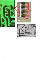
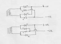
The Red lines result in a dead short across the transformer.
The green board must have the diodes orientation differently, like
K-A
A-K
K-A
A-K
The green board must have the diodes orientation differently, like
K-A
A-K
K-A
A-K
Your white lines are correct. If the diodes still are functional, desolder two of them and resolder them properly.
Best regards!
Best regards!
The board was top right and bottom green left and red lines are exactly as it. When I look at the schematic to trace down all the components then saw the diodes kinda weird. However, the amp is still working. Should I change to the white lines?
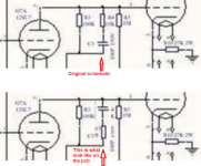
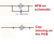
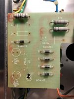
Another thing I found on the driver as well, cap and resistor reverse on the PCB and missing cap on the NFB. Omg, it was working great with a low end speakers until I hook up to the high end that was where hum noise start again. It's driving me nut So I decided to track down the whole circuit to compare with the schematic. So far that's what I have seen on the driver pcb. Still working to trace the whole PS pcb.
Another thing I found on the driver as well, cap and resistor reverse on the PCB and missing cap on the NFB. Omg, it was working great with a low end speakers until I hook up to the high end that was where hum noise start again. It's driving me nut So I decided to track down the whole circuit to compare with the schematic. So far that's what I have seen on the driver pcb. Still working to trace the whole PS pcb.
Attachments
Please post a picture of the top of the Green board. So we can see the diode's orientation. They do not look like the same board in your pictures...
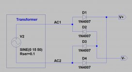
The 'bridge can be configured in two ways. See below.
The resistor / cap positions do not matter in that location. The NFB cap may not be necessary.
The 'bridge can be configured in two ways. See below.
The resistor / cap positions do not matter in that location. The NFB cap may not be necessary.
Attachments
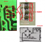
That board is wired correctly. That is why it works. It is like the top drawing in my sketch.
Look carefully again at the pictures. The one you posted with the Red and White lines, is NOT the same as the new picture.
Look carefully again at the pictures. The one you posted with the Red and White lines, is NOT the same as the new picture.
You're right. oh gezzz, my pictures were up side down. Thank you to clear it's up. Seem like some caps value have been changed on PS which it was 100uF/250v to 200uF/330v so I am not sure what effect to it.
- Home
- Amplifiers
- Tubes / Valves
- Is this full wave rectifier correct?