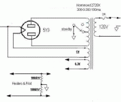
Is this curcuit ok?
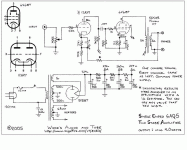
I built an amplifier from the attached schematic (hopefully it attached ok) and it sounds great but has a lot of hum. I'm trying to determine whether the hum is inherent in the circuit (due to its design) or if the hum is a result of the way I built it. The hum increases as you turn up the volume so it seems like the input is picking up hum and amplifying it along with the input signal. I have done everything I can think of to try and eliminate the hum. The heater wires are all twisted, the inputs are shielded and the output transformers are perpendicular to the power transformer etc. I was thinking of rebuilding the amp in a larger chassis and it occurred to me that the hum may be a result of the design rather than the implementation. Any thoughts would be appreciated. Thank you.
I built an amplifier from the attached schematic (hopefully it attached ok) and it sounds great but has a lot of hum. I'm trying to determine whether the hum is inherent in the circuit (due to its design) or if the hum is a result of the way I built it. The hum increases as you turn up the volume so it seems like the input is picking up hum and amplifying it along with the input signal. I have done everything I can think of to try and eliminate the hum. The heater wires are all twisted, the inputs are shielded and the output transformers are perpendicular to the power transformer etc. I was thinking of rebuilding the amp in a larger chassis and it occurred to me that the hum may be a result of the design rather than the implementation. Any thoughts would be appreciated. Thank you.
Attachments
pot?
Is this supposed to be hi-fi?? Then 500K input is a little too much.
Try to tie 100K-50K resistors from 12AX7's pins 2 and 7 to ground, unsolder the 22K screen grid resistors from the tube socket and then connect your signal straignt to those pins. You may hear some radio that way but the question is whenever the hum goes away or not.
Yes, the curcuit is supposed to be Hi-fi. I'll make the suggested mods this evening and see how it sounds. I assume if the hum is gone I need to replace the 500k pot with a 50 or 100 ohm pot, depending on which sounds better?
1st,
the power supply, The 47UF cap in the first position is way high for a 5Y3, It should be closer to 20uf. The 500 ohm resistor is rather low, I have a 1K in that position, and really, that is as low as I would go. As it is you will most likely experience arcing in the rectifier tube especially as it ages.
What are you actually using for the PT?
I am using a 300-0-300 transformer and the same Edcor output transformer.
The listed power supply voltages shown in your schematic are very low by comparison to my amp.
The Cathode resistor on the 6V6 is also IMO to small of a value. On my amp 500ohm was very hot and I upped it to 680 ohm.
But that is based on my voltages.
I measure 23V at pin 8 of the 6V6GT which the JJ brand 6V6S seems to like.
The drawing lists the feedback resistor * as 1K?? That's is a lot of feedback!
I have a 22K in that position and have tested up to 68K.
On the input(Pin2) of the 12AX7, I have a 1.5K grid stopper, and I would not go over 5.6K.
The Hum issue is most likely a grounding problem, If you post a picture ( Big Guts Shot ) it should be fairly easy to de-bug.
I originally had a hum issue in mine, but a tiny bit of re-thinking on the ground scheme resulted in a sweet hum-less amp.
I squeezed this into a Hammond 6" X 10" X 2" chassis, It was a tight fit, but not awful. I use it in my garage and have an old Celeron 750/ IBM ThinkPad as the audio source.
BTW, that is a pretty loud amp with efficient speakers.
Trout
YMMV
To kill the hum, it is better to replace the 500 ohm resistor with a 5 to 10H choke which provides much better filtering for the B+ ripple.
Johnny
Johnny
kmtang said:To kill the hum, it is better to replace the 500 ohm resistor with a 5 to 10H choke which provides much better filtering for the B+ ripple.
Johnny
Yep, I agree 110%, but he mentioned limited space.
I suspect there is another hum source, perhaps a grounding issue.
Trout,
So you have built this amplifier? What value did you use on the volume pot?
Also you said:
"On the input(Pin2) of the 12AX7, I have a 1.5K grid stopper, and I would not go over 5.6K."
So I would replace the 22k resister (at pin 2) with a 1.5k resister?
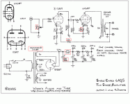
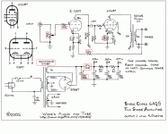
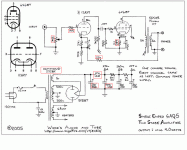
I think I have incorporated the suggested changes in this revised schematic (except for the grid stopper, I'm not sure about how to do that). I have put a red box around the changes. I put in the type of power transformer as well. Please let me know if this looks ok. I've got the amp somewhat diss-assembled trying to work out this hum but I'll try to take a couple of pictures. Thank you.
Attachments
As mentioned change that 22K resistor at the input of the 12AX7A to about 1.5K. (I typically use 1K in this location.) Make sure that you actually install the resistor right on pins 2 and 7 of the 12AX7A , I'm assuming that you have a single tube shared between the two channels.
The filament supply could be elevated rather than grounded to reduce noise pickup in the cathode circuit of the 12AX7A, and in fact the dc voltage present on the cathode of one of your 6V6 output tubes is ideal for this purpose.
Hopefully you have tightly twisted filament wiring with the wires not forming a loop around the socket, and tightly dressed to the chassis.
Otherwise make sure that the high voltage center tap goes directly to the negative side of your first filter cap and from there to your star ground - this will keep the cap charging currents away from everything else.
Your power transformer is not too closely mounted to the output transformers hopefully, and the core is mounted at a right angle relative to the output transformers?
Recommended reading if you don't have it already: Morgan Jones "Building Valve Amplifiers," and "Valve Amplifiers 3rd Edition."
Pictures would be great. Changes you have made so far are heading the right way.. This amplifier should sound very nice when sorted out. (I had a very similar one with 6BQ5 in my teens and it worked very well.)
20uF for the Plate "A" point capacitor seems pretty skimpy to me. Especially for having two single ended channels running off of it. Sure the hum may go away after adding the choke. But, it could result in a non-linear frequency response along with excessive cross talk in the lower frequencies, and intermodulation distortion.
I would simulate to make sure the rectifier won't be overloaded, but something around 220uF seems about right.
I would simulate to make sure the rectifier won't be overloaded, but something around 220uF seems about right.
Change to 1.5K looks fine.. How is the hum? I probably would not recommend going quite as far as 220uF at point A, but 20uF is definitely on the small side. I think 60uF to 100uF should be ok at this point and probably won't roach the rectifier with a 10H choke.
Stay with the 10H choke unless the voltage present at point A is too low due to the choke's dcr. In terms of capacitance use what you have on hand, I just wouldn't go much over 100uF overall.
The original drawing that this circuit was taken from is mine. Many of the resistance, capacitance and voltage values have been altered on this schematic by someone else, so this is no longer my circuit. The original amplifier runs at 275 volts B+ and uses 6AQ5s. It was built from a 1959 Zenith phono chassis and the circuit was partly Zenith, partly mine. My input pot is now 100k and I changed the 22k stopper to 2k. My amp has no hum and I would expect that if this one does there is probably a ground problem.
The 1k feedback resistor is not a lot of feedback. Look at the point that the feedback enters the first stage. The bottom cathode resistor is only 30 ohms. This kind of voltage divider does not inject much at all. If you use an unbypassed cathode resistor and place the feedback directly to the cathode, that would be a lot of feedback.
I'm glad some of you are building this. The whole reason I put it up was to encourage people towards experimentation.
Wade
I built an amp like this with a 6sn7 and two 6v6. I had a noise problem somewhat like yours. I found that problem was in the volume control. I used the 100k stereo pot that Radioshack sells. I replaced the pot- to no avail. I eventually killed the noise by bypassing the feedback tap on the volume control with a 10pf cap to ground. If your volume control doesnot have an additional tap, try bypassing from the "top" of the volume control to ground.
rdf said:Is the plate current really ~14ma (18ma plate + screen)?
No. The resistance values have been changed without changing the voltage values (on the schematic). 12.5 volts was correct for the 6AQ5 amp with a 330 ohm cathode resistor and B+ = 275v.
Wade
The last drawing posted looks pretty good.
BTW, I have the exact same transformers in my unit, The Edcor, and the Hammond 272BX.
At point A I have 345V which is still a lot higher than what you have posted. I do not have a choke in mine so it goes 20uf, 1K, 20uf, 1.5K, 20uf, 10K, 20uf.
I did not list all my voltages in my notes, So I will have to pull it out of the cabinet to get further info.
It sounds great though, once you get it bugged out I bet you will have a blast with it.
- Status
- Not open for further replies.
- Home
- Amplifiers
- Tubes / Valves
- Is this circuit ok?
