tubewade said:The original drawing that this circuit was taken from is mine. Many of the resistance, capacitance and voltage values have been altered on this schematic by someone else, so this is no longer my circuit. The original amplifier runs at 275 volts B+ and uses 6AQ5s. It was built from a 1959 Zenith phono chassis and the circuit was partly Zenith, partly mine. My input pot is now 100k and I changed the 22k stopper to 2k. My amp has no hum and I would expect that if this one does there is probably a ground problem.
Wade
I have an original 1960 Zenith service manual that might actually have the model you started out with. I had planned on scanning uploading the entire manual as it covers at large number of models.
My problem is I do not have enough online storage space to park the info online. I am certain several of the schematics are useful, it seems like more and more guys are using these types of amps as a get your feet wet projects.
BTW, is this similar to the one you started out with?
Attachments
Trout said:
I have an original 1960 Zenith service manual that might actually have the model you started out with. I had planned on scanning uploading the entire manual as it covers at large number of models.
My problem is I do not have enough online storage space to park the info online. I am certain several of the schematics are useful, it seems like more and more guys are using these types of amps as a get your feet wet projects.
BTW, is this similar to the one you started out with?
Trout,
Thanks for the schematic. Would you believe... I own one of those amplifiers too? But that is not the one this amp is based on. The one in this thread came with a 5Y3 rectifier, 6AQ5s and a 12AX7 input valve. I retained those but did away with the tone shaping controls which were incorporated into the feedback circuit. The one you provided a schematic for uses 6AU6 input valves and a 6X4 rectifier. I did the same thing to this amp, retaining the original valves, but eliminating the tone controls and configuring it to be used as a stand alone amplifier. This one provides pretty low B+ voltage to the output valves so they don't even run really very hot. The power output is low, but this amp is heavenly to listen to. I used it as my high frequency amplifier for several months when I was testing and evaluating it. The only reason it isn't in place now is that I have too many amplifiers for any sane person so each one needs to have its place in the rotation.
Thank you again,
Wade
I think I have the one you originally used also, I just found it or one like it in the manual ( Guess I should have looked longer)
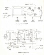
Chassis layout and schematic for 4B25(Schematic) Model 5F112?
Eh, no matter, I'll try to put this manual up temporarily and maybe someone would be interested in it enough to download and host it. It has every part, electronic parts list, and cabinet parts list also.
About 22 models, some of which are master schematics used in several model variants.
The original price on the cover was .60 cents!! 😀
Trout said:I think I have the one you originally used also, I just found it or one like it in the manual ( Guess I should have looked longer)
Chassis layout and schematic for 4B25(Schematic) Model 5F112?
Eh, no matter, I'll try to put this manual up temporarily and maybe someone would be interested in it enough to download and host it. It has every part, electronic parts list, and cabinet parts list also.
About 22 models, some of which are master schematics used in several model variants.
The original price on the cover was .60 cents!! 😀
Ha!! That's great! If you can put it up I will definitely download it.
60 cents. That's funny. The SRP on the front of my RCA Receiving Tube manuals say $1.25, $1.75 and $1.95. Inflation!
If you are still having problems, I have a question. Where is normal operation on your designs' volume control?
I ask because it seems that the 1st stage gain is quite high. If normal listening level is achieved at only a little volume control rotation, I would consider reducing the gain. I would expect "normal" listening near 50% of rotation. Excess gain in this stage will increase any hum pick up.
The two 100 Ohm resistors for the heater circuit should be matched, it might be better with none at all than 2 unmatched ones. It's not unusual to see a pot here (wiper to ground), which is then adjusted for minimum hum.
hermanv said:
The two 100 Ohm resistors for the heater circuit should be matched, it might be better with none at all than 2 unmatched ones. It's not unusual to see a pot here (wiper to ground), which is then adjusted for minimum hum.
I wish I could locate some of those old 2W 250 ohm pots. Or lets say find them at a reasonable price. I salvaged a couple from some old console stereo's but as far as current production I can not locate any. Allen Bradley used to make a really nice one with a locking shaft but of course no longer made either.
Trout
- Status
- Not open for further replies.
- Home
- Amplifiers
- Tubes / Valves
- Is this circuit ok?