No, that won't work. You can't turn a diode round because you want the voltage drop to go in the opposite direction, it simply won't conduct. If you want to use a diode to bias the cathode, it must be conducting. A 1N4148 will drop about 0.7V, and if you want higher voltages you can use LEDs. In general, the longer the wavelength of the emitted light, the lower the voltage drop.
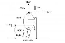
Just turn the diode around the other way and it will work. If you need more bias voltage leds work very well. You can add diodes in series to increase the effective bias voltage as needed. I can't predict what the linearity of this circuit will be like. Normally the screen grid would be set for about 1/4 the current in the plate circuit for good linearity. (1.2M resistor to supply and cap to ground in this case.)
Kevin
Edit to fix redundant remark...
Kevin
Edit to fix redundant remark...
Just turn the diode around the other way and it will work.
Only if you lose the battery. Otherwise, you end up with 2.2V.
Your caution about linearity is well-taken.
Well,it seems i forgot the way current flows😛 thanks!
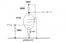
I thought that placing like so the battery would make the bias, SY.. like it's done with resistors on directly heated triodes (from which i "stole" this idea).
What if if i used a battery like:
input>---| |---- batteryplus -- batteryminus ---- grid
and connected the filament in a "conventional" way?
PS: i'm using the loadline fro mthe datasheet at around -0.7V (closest is -1V), with an anode voltage of 35V. Anode current is some 0,85mA)
OK, I think I see what you're getting at. Basically, you want the grid to be 0.7 volts negative with respect to the filament's center. So, dump the diode completely. Connect the battery "+" to ground. Across the battery, from + to -, put a voltage divider set to trickle current- like two 1M resistors in series. Connect the bottom of the grid leak resistor to the junction of the two 1M resistors. That will give you -0.75V.
Another way to do it is to run the filament from a floating CT transformer, then connect the diode from the CT to ground. From the B+, run a resistor to the diode/CT junction to put some extra current through the diode to help linearize it. In this circuit, 47K would be a good value, getting you an extra 2 milliamps.
Bypass the diode with a capacitor.
I don't understand why people use batteries at all to bias signal tubes. Surely chucking together a device consisting of various random capacitances, inductances and resistances is a fairly non-scientific approach. Especailly when a simple resistor, or even a CCS, will do the job in much more of a predictble way.
If a humble Ni-mH battery is proven to be more linear than a resistor bypssed by a film cap i would be VERY suprised... 🙂
If a humble Ni-mH battery is proven to be more linear than a resistor bypssed by a film cap i would be VERY suprised... 🙂
I don't understand why people use batteries at all to bias signal tubes.
Novelty, mostly. There are a few times when it's appropriate, but that's rare.
I don't understand why people use batteries at all to bias signal tubes.
It doesn't look like that's what he's doing. It's a 1ZH24B. If the type follows the usual convention, then it's a 1.5V heater. The battery would then act like a floating heater supply, with the diode providing the bias. Although I don't see why he doesn't just use the more common cathode bias resistor. Unlike the diode forward voltage, the resistor would allow for the bias to wander a bit to compensate for ageing and/or component error.
Furthermore, why not either provide screen voltage, or connect directly to the plate for triode operation?
Why use such a tube in the first place? There are better pentodes out there.
It's a 1ZH24B. If the type follows the usual convention, then it's a 1.5V heater. The battery would then act like a floating heater supply, with the diode providing the bias.
You got me there, Miles 😉
Well, having a bunch of them in the drawer, i would like to put them into use, like i did with the 1Zh29B (these tubes also appear as 1SH[..] and 1J[..] on ocidental writing.
Here's the revised schematic, according to your explanations.
Thanks for the help!
Attachments
Accumulators and grid-bias batteries-
Sounds like something from the Twenties, when Cycle shops recharged Accumulators, supplied 'HT' dry batteries of 90v and Grid-Bias batteries with tappings for different voltages!
Must be the Tardis effect................!
Hay guys, this is the 21'st Century! Leave the Batteries for Transistor Radios, There are so many better performing and less troublesome options out there! `
Why would anyone want to use a Battery/cell in a tube amp these days??--Beats me
Re: Accumulators and grid-bias batteries-
Because they were running out of HT and didn't want to waste it across a cathode resistor? (Grid bias) Or, perhaps because they didn't want the cathode bypass capacitor to delay recovery after overload? Or, in a low noise stage, to avoid needing an extremely large cathode bypass capacitor?
There are reasons, rare, I'll grant you, but just occasionally, a battery is the best solution.
Alastair E said:Why would anyone want to use a Battery/cell in a tube amp these days??--Beats me
Because they were running out of HT and didn't want to waste it across a cathode resistor? (Grid bias) Or, perhaps because they didn't want the cathode bypass capacitor to delay recovery after overload? Or, in a low noise stage, to avoid needing an extremely large cathode bypass capacitor?
There are reasons, rare, I'll grant you, but just occasionally, a battery is the best solution.
Why would anyone want to use a Battery/cell in a tube amp these days??--Beats me
I've seen this done just twice. Once in an RF VT amp that didn't require very much bias voltage anyway. Here, a battery will always provide bias to prevent out of SOA dissipation in case the RF drive is lost.
The other time was a 10GHz preamp that used gallium arsenide JFETs. In that case, battery bias allowed the sources to be connected directly to the ground plane to avoid excessive inductance in that part of the circuit, where, of course, you don't want the degeneration.
Still, if you need an external source of small bias voltages, a 555 could certainly be used instead of a battery.
A lot of people around here use battery bias with dhts and small iht's in pre-amplifier circuits. I used it in the cathode circuit of the lower tube in a white cathode follower circuit in my headphone amplifier where the bias required is just 1.25V. Personally I don't think it sounds too good in this application and will be going back to conventional fixed grid bias from a separate supply.
I have heard several line stages where this same approach was used that sound very good. The basic idea is that the battery provides very low impedance at audio frequencies and obviates the need to use a large electrolytic capacitor in the cathode circuit. Some people seem to be phobic about use of electrolytics anywhere.. I think a nice little blackgate or nichicon muse is just fine if fixed bias is not suitable.
9V batteries provide just the right bias voltage for 26's and 27's in some of my pre-amplifier circuits and avoid the complications of an additional low noise bias supply, and will effectively last the shelf life of the battery. This works extremely well...
Kevin
- Status
- Not open for further replies.
- Home
- Amplifiers
- Tubes / Valves
- Is this circuit I drew ok?