Greetings!
I am building a guitar amp and I need a power amp of 100 W in 8 ohm. Would the folowing schematic be good, those videorrocola people claim it to be. Or would j be better of with a cheap tda7293/4 board from ebay? I dont need an amp that is high fidelity i need an amp capable of sustaining power without burnig out as i will mainly use it for metal. I would kindly ask for your Professional opinion on this.altough a really doubt that this amp is capable of 100w into 8 r, mainly beacuse of5200 transistors at output. 🙂
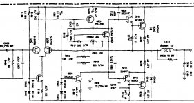
Link to schematic : construya un amplificador monofonico de 100 watts version 2.0
I am building a guitar amp and I need a power amp of 100 W in 8 ohm. Would the folowing schematic be good, those videorrocola people claim it to be. Or would j be better of with a cheap tda7293/4 board from ebay? I dont need an amp that is high fidelity i need an amp capable of sustaining power without burnig out as i will mainly use it for metal. I would kindly ask for your Professional opinion on this.altough a really doubt that this amp is capable of 100w into 8 r, mainly beacuse of5200 transistors at output. 🙂
Link to schematic : construya un amplificador monofonico de 100 watts version 2.0
If you never diy an amp before then it is a little bit hard for you to build one of these amp without a PCB.
First build amp better buy a complete kit of components and PCB which is more easy for people to start and succeed.
First build amp better buy a complete kit of components and PCB which is more easy for people to start and succeed.
If you never diy an amp before then it is a little bit hard for you to build one of these amp without a PCB.
First build amp better buy a complete kit of components and PCB which is more easy for people to start and succeed.
The pcb is not a problem, building either, this would be my 15 or 20 th amp project, but the first of this power. Before i used to build amps with 20 to 25 w hifi quality. I just want to know if the circuit is good or bad. I know how a tda7293 performs, is this better or worse than that? Thanks for a Quick reply.
the circuit is simple and for starter, with 5200 ouput trs. it can output 80W~100W with enough voltage supply.
You can select a more stable amp circuit to built, there are many same simple but better circuits around.
You can select a more stable amp circuit to built, there are many same simple but better circuits around.
the circuit is simple and for starter, with 5200 ouput trs. it can output 80W~100W with enough voltage supply.
You can select a more stable amp circuit to built, there are many same simple but better circuits around.
Ok, if i decide to build it what EU substitute would you recomend for transistors 2sc2229 do they really need to be high voltage for this aplication, beacuse these are.
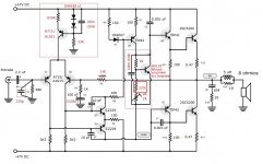
You can try this, it is an ab international AB200 PA amp circuit, suitable to use as a guitar amp.
Attachments
Last edited:
Thanks, I will look at this one. Can I use bc or bd substitute for the low power transistors? Like in the differential pair, can I use bc547 for example?
Ok, if i decide to build it what EU substitute would you recomend for transistors 2sc2229 do they really need to be high voltage for this aplication, beacuse these are.
for this circuit and the supply voltage, 2sc2229 at least need a 80V Vce trs.
You can use Toshiba 2sc2705
Last edited:
Thanks for all the info, so if i understand correctly, if in the old circuit i were to replace the diode and 330 ohm bias circuit with a vbe multiplier the amp would be good? could i ask you to tell me where to connect it in this diagram?i am not as expirienced to kow that. Many thanks in advance!
Attachments
I forogt to say i would really like to build that circuit beacuse I have almost all the parts and a ton of 2sc5200🙂
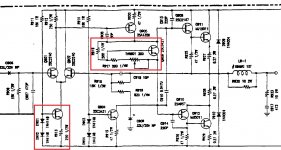
so if i understand correctly, if in the old circuit i were to replace the diode and 330 ohm bias circuit with a vbe multiplier the amp would be good?
Please select and change the circuit as the red area, there is a Vbe multiplier with suitable resistors/VR values for it's application.
The original amp gain is too high, please change R5 68K to 33K.
Vbe multiplier trs can use tip41
Attachments
Last edited:
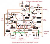
R6, R7 and R9 can also change all to 100 ohm for a little bit higher trs. current of the second stage which help for better output sounding.
The Vbe multiplier has a little change, a 220 ohm resistor added for bias safe setting, pls check the diagram.
Many thanks for all your help. As soon as i can i will build a prototype and do some testing. I will surely report back on how it goes. I have all transistors except the a1015 for which i plan to use a bc557, and the c2229, for which i havent located any replacement in the bc or bd series yet. i will look it up as soon as i get home. One more question, could bd140, bd139 be used just for testing instead of tip 41, tip 42?
I must say I really appreciate all the help, which i certanly wouldnt get from Slovenian forums. They are uselles🙂.
Have a nice day sir
I must say I really appreciate all the help, which i certanly wouldnt get from Slovenian forums. They are uselles🙂.
Have a nice day sir
I have all transistors except the a1015 for which i plan to use a bc557, and the c2229, for which i havent located any replacement in the bc or bd series yet. i will look it up as soon as i get home. One more question, could bd140, bd139 be used just for testing instead of tip 41, tip 42?
BD139,BD140 Vceo is only 80V, so that the power supply voltage should not over +- 40V DC, but if you only build for a prototype, you can temporarily use them to replace the TIPs and the c2229 trs. for +- 47V DC supply rails.
TIP transistors should never be used for VAS duty (Q5). Sounds like garbage. Really. Can you get KSA1220 (ON/Fairchild)? It makes a good driver transistor at these voltages and power levels too, and the NPN is available anywhere the PNP is. In that circuit you would need to add about 30pF collector to base on Q5 if you used the better part to keep the effective capacitance the same and keep the amp stable. But a fixed capacitor always sounds better than a non-linear one inside a transistor that is really too large for the job.
Might have been one reason the TIP42 was used - having a “built in” Miller capacitor. But that’s not the best way to do it by far.
Might have been one reason the TIP42 was used - having a “built in” Miller capacitor. But that’s not the best way to do it by far.
- Home
- Amplifiers
- Solid State
- Is this amplifier really stable and good?