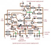
I made a prototype PCB layout.
Q7 emitter is connected to the output, revised the layout for this
Attachments
Last edited:
Thanks for a very good layout and every thing. I have made the prototipe and I observe foloving behavior: on +-24 volt supply there is 1 mA of quiescent current on the + rail. The base voltage on Q 6 and Q7 are 1 volt. The signal doesnt get far I traced it to the base of Q4 but any thing further on the signal is lost. (i used 1 khz on generator and looked with a scope). There is nothing at the output just a small dc offset. When adjusting the bias pot nothing happens. I didnt have a lot of time today so I will do further measurments tomorrow. I used bc557 for q1, q2, current source. Q3 and Q4 are bc547. Q5 is bd 140, vbe multiplier is bd139 and output tran. Are c5200. Any toughts where to search for the problem tommorow?
I wish you a Nice weekend.
I wish you a Nice weekend.
on +-24 volt supply there is 1 mA of quiescent current on the + rail. The base voltage on Q 6 and Q7 are 1 volt. The signal doesnt get far I traced it to the base of Q4 but any thing further on the signal is lost. (i used 1 khz on generator and looked with a scope). There is nothing at the output just a small dc offset.
Sorry to tell, it must be something wrong with your layout, this circuit is quite simple, if build with all new parts and correct layout, it must work
Great chance you make the small signal trs. C/E pins reverse, please careful check your layout again
I cant right now im away tommorow i will check every thing and give some pictures. Of course there is a posibillity i turned something around. I will check further on tommorow.
My activities ended prematurely today so I took another look at the amp. I found one of the 1n4148 diodes open. I dont have any more so I replaced the whole transistor supply for differential pair with a zener diode and the amp works, but it distorts slightly. I can adjust the idle current. Could I use something else instead of those two 1n4148 diode?
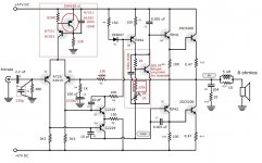
Or just a big resistor to bias the diff pair. 68k for a 47 volt supply, less if your voltage is lower. Looks like you want somewhere in the neighborhood of 0.7 mA, a little more wouldn’t hurt. If you just used a zener you may have too much current in the diff pair and following stages.
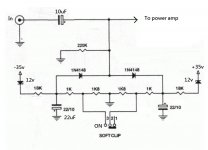
Yes, this works very well now. I did the power measurment at 4 ohms as i dont have an 8 ohm dummy load and it outputs aaprox. 56 W. That is at supply voltage of 2x35 volts, and no clipping. I will have to get some c2229 s to replace those two bc547 s which wont handle the higher voltage. Filter caps are 1000uF per rail. Thats to liitle i will upgrade it to say 4700 UF par rail. I will do these things as soon as i can and report back. I should mention that to my ears this amp sounds fine and there is no noise whatsoever. One more question. Since this is going to be a guitar amp, is there a way to limit the user from driving it into clipping? I assume not but i ask anyway. A Big THANKS for every thing so far you are really kind to provide so much info and even schematic mods. Thanks again and again.. 🙂

Greetings!
One more question for the professional🙂
I am Please with the amp as i said, but could I make it work with a 4 ohm load? And for that purupuse could the output transistors be Mj15022. Its just i have about 50 of these and I would like to use them up?
Any suggestions?
Thanks in advance,
electronicsman
- Home
- Amplifiers
- Solid State
- Is this amplifier really stable and good?