I asked this in the chip amp section but it may be more appropriate here. Can anyone tell me if this amp is bad based on what I describe? Or ask more specifics from me on it? Is it possible that I've overlooked something obvious in setting it up?
Finished Board New TPA3123 2 1 Digital Power Amplifier Board Subwoofer Output | eBay
Came last week. Finally got around to bench testing it. Used a 15vdc 3amp Toshiba SMPS. The mains are 3.5inch Vifa 8ohms and "sub" is a 4inch Dayton Neo woofer. Music input from a preamp. Checked, double checked, polarities with DMM.
Turned on the music, plugged in the power supply, and nothing. Just a steady approx 3 beat per second low volume "blip" coming out of the main speakers. Nothing out of the woofer. Volume, treble, and bass level controls have no affect whatsoever.
I swapped the power supply for a 19vdc 4amp Sony SMPS and the result was unchanged. I disconnected the signal input. No change. Same 3bps blips.
I'm well within my 15day return period and the guy's got a big store with 98.9 approval so I'm not too worried yet. But I'd like to be certain that the amp is bad before going through all the trouble to return it for another.
Over at TI forums a mod tells me.....
....if you put the power supply leads backwards, I assure you the IC is blown. I'd say to save your sanity just buy another one (board) for $23
This happens. On everything I build, I include a diode at the power supply input to prevent it. Only costs a couple of cents and some voltage drop.
Thanks for that suggestion vacuphile. What value/package diode would you recommend for this application? 15 to 20 vdc. 3.0 to 5.0 amp SMPS. Powering a 20w/ch tripath board. And what kind of voltage drop are we considering?
By a Google search this one suggested itself.
Avalanche diode - This diode conducts in reverse bias condition where the reverse bias volage applied across the p-n junction creates a wave of ionization leading to the flow of large current. These didoes are designed to breakdown at specific reverse voltage in order to avoid any damage.
Avalanche - Vishay Semiconductor Diodes Division - Avalanche | Dynamic Catalog | DigiKey Corporation
Unless you might suggest anything more generic. I have a drawer full of odds/ends in the shop with scattered, caps, resistors, diodes etc.
It really does not matter that much, as long as the continuous forward current rating is higher than what your amplifier will draw. Something like this would do Buy Rectifier & Schottky Diodes Diode Schottky 40V 5A DO-201AD Lite-On SB540 online from RS for next day delivery.
Since I've gotten very little response to questions about what I'm trying to do here and in two other threads I wonder if you would add anything to the following, especially since I've ruined one amp at the power supply end. I'm a bit concerned about the signal input I'm using....
From my post here in another thread.....
http://www.diyaudio.com/forums/soli...level-off-reciever-help-me-id-these-pins.html
And a response to another member's similar question in the Tube amp section of the board.....
"Its always good to have a cap in series out, with a resistor (or volume pot) across it to ground, to create a stable and high output resistance for the preamp to 'see'."
Or are they only considering pre-amp stage voltage potentials expected of tube amps and not solid state?
That's what is meant by an "evaluation board" I suppose. Bare bones. Implementer is expected to include his own versions of protective circuitry according to his power source and signal input.
Sounds like he's also suggesting that I tap into the signal ENTERING the volume pot (and then only using the volume control on the TPA3123 board) rather then using the signal leading OUT of the pot.
In that other thread high dc voltage at the signal output is the fear. What is "high" measured on the DMM? Below a limit such protection isn't needed?
thanks extremely for any head's up on any of this. i ordered a replacement last night and it ought to be here in a week
From my post here in another thread.....
http://www.diyaudio.com/forums/soli...level-off-reciever-help-me-id-these-pins.html
And a response to another member's similar question in the Tube amp section of the board.....
Even after locating the right pins, is it generally necessary to create this circuit ...nazaroo Quote:
Originally Posted by hesee
I did create pre-out, by grabbing signal after volumecontrol, before first condensator. Seems to work just fine.
Make sure you are not directing any DC high voltage out of the amp/preamp and into some other piece of equipment not expecting to have to block High Voltage.
Check for D.C. on the signal out you have created.
Even though the circuit might work for a while,
the voltage rating of the input cap in the other equipment
you want to plug into might only have a low voltage blocking cap in its input circuit.
Eventually the input cap on the other equipment will burn out and damage may ensue.
Its always good to have a cap in series out, with a resistor (or volume pot) across it to ground, to create a stable and high output resistance for the preamp to 'see'.
Then you take the signal out from the other side of the cap (and resistor) or from the wiper of the pot (if you put one in) to the new output jack.
That way, if there is any High Voltage DC where you are tapping it, it won't get into other equipment or hurt anyone.
Use a 600 volt output cap, say .1 uF and a 200k - 500k volume pot or resistor. If you aren't getting enough bass, just put two caps in parallel.
"Its always good to have a cap in series out, with a resistor (or volume pot) across it to ground, to create a stable and high output resistance for the preamp to 'see'."
Or are they only considering pre-amp stage voltage potentials expected of tube amps and not solid state?
That's what is meant by an "evaluation board" I suppose. Bare bones. Implementer is expected to include his own versions of protective circuitry according to his power source and signal input.
Sounds like he's also suggesting that I tap into the signal ENTERING the volume pot (and then only using the volume control on the TPA3123 board) rather then using the signal leading OUT of the pot.
In that other thread high dc voltage at the signal output is the fear. What is "high" measured on the DMM? Below a limit such protection isn't needed?
thanks extremely for any head's up on any of this. i ordered a replacement last night and it ought to be here in a week
Last edited:
vacuphile, is the diode you suggest considered a consumable part in the case of mishap? Or does it simply block reversed DC and remain intact?
It prevents reverse polarity by acting like a one way valve, current passes in the forward direction but not in reverse.
I understand that is essentially how diodes function. What I'm wondering is how substantial will be the voltage drop and whether the diode survives the reverse polarity without harm.It prevents reverse polarity by acting like a one way valve, current passes in the forward direction but not in reverse.
Can you help me with those two questions as applies to this amp and supply?
I just ordered six of these to install on the two boards I'll have on the benchtop and to keep on hand....
CDBC540-G Comchip Technology | 641-1126-1-ND | DigiKey
Peace,
The diode will survive reverse polarity up till the break down voltage, which should be higher than your supply voltage.
Voltage drop will be between 1.5 and 0.2 Volts for the ones I have measured, but you can find this figure on the specsheet for the part. It is called the forward voltage.
The part you have has a break down voltage of 40V, so the supply voltage should be lower than this, and you will loose .55Volts. You will find this under forward voltage om the specsheet.
Keep in mind that at 3A and approx. 0.6V voltage drop, the diode dissipates around 2W. For a small diode in free air, this might already be a lot....
Greetings,
Andreas
Greetings,
Andreas
Keep in mind that at 3A and approx. 0.6V voltage drop, the diode dissipates around 2W. For a small diode in free air, this might already be a lot....
Greetings,
Andreas
.... where do those periods lead?🙂
Are you suggesting that the SMD package may not dissipate heat well enough over time? What are the options/remedies. Approx 7.5 x 6 mm is a pretty large SMD. I suppose a tiny heat sink could be cemented onto it?
2W metal film resistors are approx. 11x4mm, and they get incredibly hot if they're really dissipating their rated 2W. Usually you derate them by a factor of 2-4 to keep the temperature below reasonable limits.
Choose a beefy diode and keep it well below its specs.
Andreas
Choose a beefy diode and keep it well below its specs.
Andreas
Is this going overboard?
I have the parts on hand, I think, to rig that up. The size of the diode is not important here correct? It's just energizing the relay?
A single power mosfet is mentioned often on the web as well for circuit protection. But I don't possess the skill to calculate for and identify the right IC in Digikey's catalog.
Would the Si4838DY or the IRLML6344TRPBF be fine for the voltage/amperage and load I'm working with?When the DC voltage is connected properly, the MOSFET's gate is pulled high relative to its source, which turns it ON. In this case, the FET behaves like a low-value resistor. When the DC voltage is reversed, the gate is pulled LOW relative to its source, and the FET turns off. Simple as that. Mostly.
You must choose a MOSFET with a low enough turn on voltage that it's FULLY turned on at your minimum operating voltage, and has a low enough RDSon at your operating voltage that your voltage drop will be low enough for your system to operate. I show a Si4838DY that will fit the bill for many projects. At Vgs = 2.0V, it has an ON resistance of only 0.003 ohms! And it can handle up to 60 Amps, so it's effective for low and high current applications. It's expensive, at over $3.00 each though ($1.50 in quantity). For less demanding applications, perhaps a IRLML6344TRPBF will better fit the bill. It's only $0.50 ($0.13 in quantity).
As your operating voltage goes up, a whole plethora of transistors open up, that may be better suited for your application, and cheaper. Just be sure to look at the RDSon vs. Vgs chart on your proposed transistor. Once you learn to peruse the DigiKey search engine and scan the data sheets, you can find transistors pretty quickly.
By the way, carefully check to make sure that you don't reverse the Source and Drain of the transistor! If you do, the body diode of the FET will conduct during reverse polarity connection, and you'll fry your circuit.
Last edited:
Looking for a miniature relay I found this buried way back in a drawer...

Will it fit the purpose?
Will it fit the purpose?
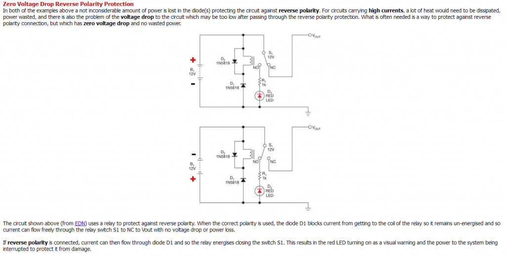
The relay circuit is nonsense.
The time it takes to energize the relay coil and mechanically move the contacts could well be long enough to fry your circuit - so this shouldn't be called a 'protection'. Even worse, it gives false security.
Andreas
The time it takes to energize the relay coil and mechanically move the contacts could well be long enough to fry your circuit - so this shouldn't be called a 'protection'. Even worse, it gives false security.
Andreas
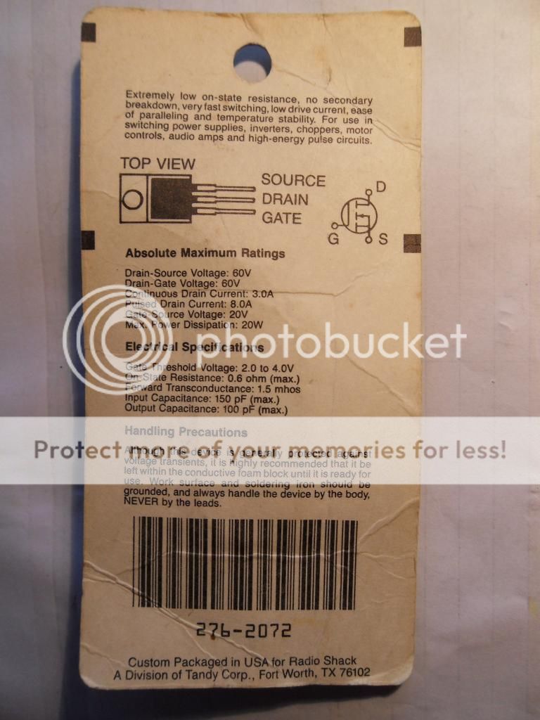
And further reading suggests the mosfet approach req's a pmos fet instead of my Radio Shack nmos fet. nmos fet can be used on the low side of the inputs but comes with certain disadvantages.
Would anyone here be so kind as to help me identify the correct pmos fet to use in this case?
and....
Would anyone here be so kind as to help me identify the correct pmos fet to use in this case?
and....
I 'd really appreciate some translation of all that for my purposes. SMPS up to 20vdc at 5amps. Amplifier will likely draw no more than 2amps.P-Channel FET
Reverse Polarity Protection Using a P-channel MOSFET
For the ultimate in low voltage drop and high current capability, replacing the PNP transistor with a P-channel MOSFET as shown in this circuit, can’t be beat. Please note that the FET is actually installed in the reverse orientation as it would normally – the drain and source are reversed. This orientation is necessary so that the slight leakage current through the FET’s intrinsic body diode will bias the FET on when the polarity is correct and block current when reversed, thus shutting off the FET. Here is a real nice video tutorial of how the magic works.
If the supply voltage is less than the FETs maximum gate to source voltage (Vgs), you only need the FET, without the diode or resistor. Just connect the gate directly to ground. I have found that most smaller FETs maximum Vgs is 12 volts or less, which can be a problem for 12 volt (or higher) supplies. If after checking your FET’s spec sheet, you find that Vcc could exceed the maximum Vgs, then you must drop the voltage between the gate and the source.
The circuit shown does exactly that by a very clever means. By inserting a zener diode with a voltage less than the maximum Vgs, it limits the voltage to a safe level between the gate and the source. You will need to calculate the resistor value so that it will provide enough current to properly bias the zener diode chosen. The zener diode’s spec sheet will provide the minimum current required to achieve the zener breakdown voltage, and you can then calculate your resistor value from that.
May I suggest using a reverse polarity crowbar diode?
Just wire it in parallel with the amplifier after a fuse-link wire, a single strand from a typical 16ga stranded wire will pass all the current needed. If hooked up with reverse polarity the diode will crowbar the link.
Just wire it in parallel with the amplifier after a fuse-link wire, a single strand from a typical 16ga stranded wire will pass all the current needed. If hooked up with reverse polarity the diode will crowbar the link.
Candidates for the Darwin Award should not read this author.
Could be oh so true in this case. Have I made it evident enough that I lack EE background?
When you say "fuse link" I translate that to mean that it is literally a fuse. So a single strand of typical 16ga stranded will burn and break before any damage is done?
You'd have to explain "crowbar the link" to me if I have any hope of using your suggestion.
The diode is set up directly after the fuse-link wire, both the diode and the fuse-link will pass tons of current.
The cathode (marked with a band on one end of the diode) end of the diode goes to the + of the supply voltage, the other end goes to the - of the supply voltage.
The diode will do nothing if the supply is hooked up properly. If the supply is hooked up backwards the diode turns on an throws a dead short across the power supply, thus acting like a crowbar and vaporizing the tiny strand of wire (the fuse-link). I suggest using a 3A diode, any voltage rating will do.
An externally hosted image should be here but it was not working when we last tested it.
Last edited:
- Status
- Not open for further replies.
- Home
- Amplifiers
- Solid State
- Is this amplifier faulty?