Why is reverse polarity circuit protection so alien an idea to everyone? I'd have thought that I could just get a circuit protection IC on a chip from digikey instead of having to post at three or four boards to get advice on diy'ing it. I got 150 views on a very active EE board with no comment at all.
I'm sorry, I'm lousy at following verbal explanations. This is what I imagine you are describing? Isn't this still capable of frying the circuits on the amp even in the brief time that it takes the link to burn?

Before I'd logged back in here I had considered another temporary approach. Just a separate little testing board used between the power supply and amplifier while bench testing various configurations and then when ready I'll just hard plumb the powersupply to the amp and be done with it. Two power in terminals and two power out.

Would this work? Would the led indicate a problem?
I'm sorry, I'm lousy at following verbal explanations. This is what I imagine you are describing? Isn't this still capable of frying the circuits on the amp even in the brief time that it takes the link to burn?
Before I'd logged back in here I had considered another temporary approach. Just a separate little testing board used between the power supply and amplifier while bench testing various configurations and then when ready I'll just hard plumb the powersupply to the amp and be done with it. Two power in terminals and two power out.
Would this work? Would the led indicate a problem?
Last edited:
The diode goes across the amps DC input and the fusable link goes in series with the battery, that way the fuse blows when the supply is reverse polarized.
Or you put the diode in series with the DC input inside the amp, that way the amp wont care what polarity the supply has as it will block any current from flowing in the reverse direction, though you loose 0.7V this way as diodes have a forward direction voltage drop, not a big deal though.
Or you put the diode in series with the DC input inside the amp, that way the amp wont care what polarity the supply has as it will block any current from flowing in the reverse direction, though you loose 0.7V this way as diodes have a forward direction voltage drop, not a big deal though.
Last edited:
May I suggest using a reverse polarity crowbar diode?
Just wire it in parallel with the amplifier after a fuse-link wire, a single strand from a typical 16ga stranded wire will pass all the current needed. If hooked up with reverse polarity the diode will crowbar the link.
I would *not* recommend that approach. It has the same weakness as the complicated relay solution posted earlier: It takes time to burn the fuse link - unless you definitely know that your circuit survives wrong polarity for some time, this does not give any reasonable safety.
A series diode offers real protection at the expense of 0.7V voltage drop and some power dissipation. An 'inverted' version of the relay (meaning: relay needs to energize in order to supply power to the amp circuit) circuit offers real protection at the expense of part costs and the power consumption of the relay, but without the voltage drop.
Andreas
"This is what I imagine you are describing? Is"
No, the fuse link must go in the line before everything. The way you have it drawn it will serve no purpose.
"It takes time to burn the fuse link "
So what, there is a short across the amplifier until the fuse-link opens. It works, I used it on Yamaha TC800G tape decks in the 70s. If you can stand the voltage loss and deal with the heat, you could use a series diode as well.
So what, there is a short across the amplifier until the fuse-link opens.
Admittedly, the diode should keep the reverse voltage below 1V - which is hopefully safe. A series diode protects less destructively and if 0.7V voltage drop is a problem, the power supply is at the margin of being undersized anyway...
Andreas
wow, you're right on that one. now you see how i ended up in this trouble to begin with. no, i don't work in a nuclear power plant😱The way you have it drawn it will serve no purpose.
Is it really that difficult to calculate a value for a pmos fet? (unfortunately for me that answer is yes).
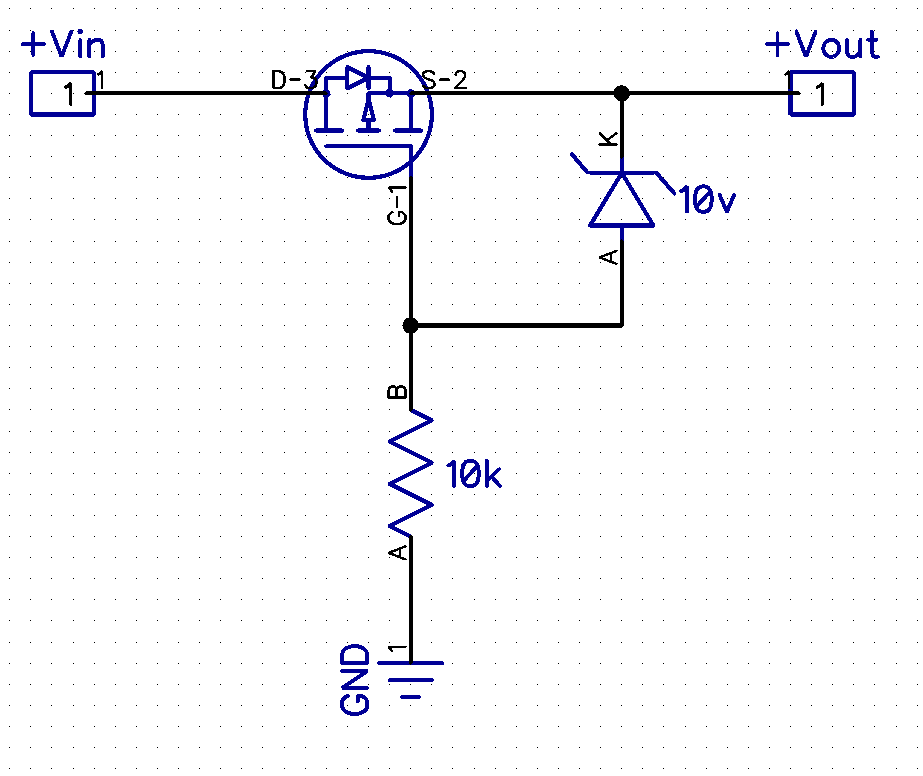
If the supply voltage is less than the FETs maximum gate to source voltage (Vgs), you only need the FET, without the diode or resistor. Just connect the gate directly to ground. I have found that most smaller FETs maximum Vgs is 12 volts or less, which can be a problem for 12 volt (or higher) supplies. If after checking your FET’s spec sheet, you find that Vcc could exceed the maximum Vgs, then you must drop the voltage between the gate and the source.
The circuit shown does exactly that by a very clever means. By inserting a zener diode with a voltage less than the maximum Vgs, it limits the voltage to a safe level between the gate and the source. You will need to calculate the resistor value so that it will provide enough current to properly bias the zener diode chosen. The zener diode’s spec sheet will provide the minimum current required to achieve the zener breakdown voltage, and you can then calculate your resistor value from that.
Last edited:
The irs2092 class d chip also has a click mode.
It does this if the power supplies haven't come up right or for some reason there is an overload on the output.
Might be worth checking your speaker wiring again before giving up and sending it back.
It does this if the power supplies haven't come up right or for some reason there is an overload on the output.
Might be worth checking your speaker wiring again before giving up and sending it back.
The irs2092 class d chip also has a click mode.
It does this if the power supplies haven't come up right or for some reason there is an overload on the output.
Might be worth checking your speaker wiring again before giving up and sending it back.
Please, please, for the love of god would anyone with a suggestion feel free to presume my ignorance. Be specific in what you are suggesting. The "subwoofer"output is already paired. No problem. The stereo outputs are shared ground. So how could the speaker wiring affect the outcome?
Is the "click mode" what I described at the beginning of the thread? About three clicks/blips a second when running, plays no content, and is unresponsive to any commands.
Don't know why the "inverted polarity" discussion carried for so long, when it was *never* determined that a polarity inversion took place.
And if it did, the amp is toast, no after the fact protection will reverse that.
As of the tick tick tick sound, it may mean that the SMPS is not up to the task, or the amplifier was miswired, or both.
*Maybe* it's a bad board, not impossible, but unlikely .... unless it was killed by reverse polarity or wrong connection, but that's only an unsubstantiated theory so far.
If you really can't trust yourself to wire up a power supply correctly you can always use a bridge rectifier before the circuit. Then you can wire up the power either way round and it will still work.
The question then becomes, however, can you trust yourself to wire up the bridge rectifier correctly?
We used to do this with some military radios where there was no connector-based poka-yoking. The guys however do have the excuse that they may be working under fire...
The question then becomes, however, can you trust yourself to wire up the bridge rectifier correctly?
We used to do this with some military radios where there was no connector-based poka-yoking. The guys however do have the excuse that they may be working under fire...
That's the point.
The bridge rectifier may be wired backwards and *guarantee* to blow the amplifier, no matter how you connect the PSU.
Being realistic, diode protection is fully justified only in guitar pedals, where technically compromised guitar players may use the wrong power brick polarity.
There, both there is a high probability of happening, and a humble 1N4002 has enough "balls" to do the job.
Check Boss pedals schematics and many others.
Well it comes down to enhancing your odds.... like anything else.
This little three piece circuit works like a gem.
It's temporarily wired to the amp while I'm bench testing. All I have to do is wire it once correctly and from that point on it protects the board from any mishap and the led lights when I've screwed up. Get it right once.... and it's 100 percent effective. Just an off-the-shelf red LED and a 1K resistor covers the range I'm working with. When all the testing is done I remove it and hardwire the power supply I've finally chosen and I'm good.
Last edited:
- Status
- Not open for further replies.
- Home
- Amplifiers
- Solid State
- Is this amplifier faulty?