I am experimenting a bit and added a few more components to an existing crossover circuit board. I was a bit worried about heat but wasn’t aware that coupling between inductors was also a thing to worry about.
I need to add an LPad to this and found a spot that would work, but I’m thinking I probably should pull everything apart and mount them to a piece of timber rather than trying to squeeze more on.
Does anyone think it’s ok as is?

I need to add an LPad to this and found a spot that would work, but I’m thinking I probably should pull everything apart and mount them to a piece of timber rather than trying to squeeze more on.
Does anyone think it’s ok as is?

The one on the right is series to the woofer, the middle is across the tweeter, top is series to mid and the ferrite core on the left is across the mid.
The top one would be coming off the board if I add a series resistor prior to the mid circuit, or the other thing I’m considering is an LPad directly on the back of the mid driver
The top one would be coming off the board if I add a series resistor prior to the mid circuit, or the other thing I’m considering is an LPad directly on the back of the mid driver
I could outline a way to test for coupling.
To cut to the chase, the top inductor would be the one to move (if one were the number) since it is involved in both of the (visually apparent) potential couplings.
To cut to the chase, the top inductor would be the one to move (if one were the number) since it is involved in both of the (visually apparent) potential couplings.
For Reference....I am experimenting a bit and added a few more components to an existing crossover circuit board. I was a bit worried about heat but wasn’t aware that coupling between inductors was also a thing to worry about.
I need to add an LPad to this and found a spot that would work, but I’m thinking I probably should pull everything apart and mount them to a piece of timber rather than trying to squeeze more on.
Does anyone think it’s ok as is?
View attachment 1459709
Attachments
Just rotate it. Point the hole up,I could outline a way to test for coupling.
To cut to the chase, the top inductor would be the one to move (if one were the number) since it is involved in both of the (visually apparent) potential couplings.
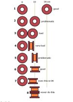
I'd also point out that while these two look to be the same case (looking across the board from the side), the one in the diagram is placed on a flat surface so it's not in the middle (the one standing on it's rim is higher than the one flat on the bench), so it's more like the one I circled in orange above.

Turn the one marked "-42", 90 deg.
Now all the three inductors are orthogonally oriented - which is good.
But as Allen is indicating - for this to be effective, their centers (of gravity) need to be in one and the same plane - which is not so easy to achieve... haven't considered that I have to say... is it true?
//
Now all the three inductors are orthogonally oriented - which is good.
But as Allen is indicating - for this to be effective, their centers (of gravity) need to be in one and the same plane - which is not so easy to achieve... haven't considered that I have to say... is it true?
//
I’ll do it if I need to, just trying to find out if I need to or not.A larger pcb is a no go?
no goal, this is an existing PCB that I have added more components to, to adjust the crossover points and slope.What is the goal of having all components so close together?
They are slightly offset. I could try to raise the ferrite core one my a few mm so that the centres are aligned, but not sure I have enough length in the leads.I'd also point out that while these two look to be the same case (looking across the board from the side), the one in the diagram is placed on a flat surface so it's not in the middle (the one standing on it's rim is higher than the one flat on the bench), so it's more like the one I circled in orange above.
View attachment 1459769
I do think it's worthwhile trying to understand the mechanisms involved, but in practice there is a level of unpredictability so I'd be uneasy guessing the result. This is something amplifier builders will attest to when it comes to placing power transformers near output transformers or low level amp stages or interstage transformers. The usual tricks often work but the only way to be sure is either to get distance or to measure while moving them about.
- Home
- Loudspeakers
- Multi-Way
- Is this a bad crossover layout