Did you try this topology?
8932 GNFB is on chip, with a gain of 30 or 36dB. That might throw a wrench into the schematic you posted, which assumes amplifiers running open loop, with the loop closed by the components on the schematic. Those open loop amplifiers are assumed to have higher gains (60-120dB).Thank you OllBoll,
it looks like I had the same idea: to buy ready 8932 amp (in the price of a single chip) and modify it to transconductance mode.
The 2 pcbs which I bought (didn't arrive yet) are 35W mono amp, this means they are working in bridge mode, so I will need to buy NE5534s and use them like in post 10. I need additional +-15V ps.
It is a bit unclear for me how to modify the circuit with soldered 8932, it looks like gnfb net is hiden in the chip?
so ¯\(ツ)/¯
maybe OllBoll had instability and output resistance problems because of this, mixed voltage and current feedback might created negative or complicated output resistance?
I guess that class D chip with olg >80dB of the gain doesn't exists?
Back to the question from the post 1?
Anyway soon I will check if 8932 sounds good as designed...
so ¯\(ツ)/¯
maybe OllBoll had instability and output resistance problems because of this, mixed voltage and current feedback might created negative or complicated output resistance?
I guess that class D chip with olg >80dB of the gain doesn't exists?
Back to the question from the post 1?
Anyway soon I will check if 8932 sounds good as designed...
The amount of gain wasn't the problem. 36 dB is high such that if we use say 20 dB of gain for feedback we should be able to get output impedance of say 100 ohm. High enough for it to be good enough.
I'm not an expert so this is a guess given my limited understanding but I believe that the problem was high frequency phase shifts. I could get the output impedance to 80 ohm @ 1 khz but then I had to lowpass the current feedback so it wasn't even close to uniform over the frequency spectrum. Or maybe the fact I fed the feedback into both sides could have been the problem instead of only applying feedback on one side and mirroring the current with the other.
When I've played around with class A amplifiers like an F6 clone with current feedback instead of voltage feedback the main reason has been capacitors on the feedback path. Especially output capacitors which are a problem unless combined with DC voltage feedback. I believe that a BTL setup makes the most sense with the 8932 that complicates things since now the output has a different DC potential to the input pins. At least if I remember correctly I measured the input pins and found a different voltage, at least with a asymmetrical supply which my off the shelf boards used.
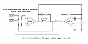
The problem of course is if course getting the feedback stable. One idea I've been toying around with is the following setup in the image: Using a quad transformer to use one winding for the current sense resistor, the other for the input. So basically trying to passively solve the DC potential difference of the external input, the 8932 input and the speaker output rsense all in one go. Would it work? Maybe? Or maybe still oscillates at rail voltage but might be fun to try. Would have to modify the off the shelf board but should be doable.
Attachments
What was the circuit you tried that didn't work?The amount of gain wasn't the problem. 36 dB is high such that if we use say 20 dB of gain for feedback we should be able to get output impedance of say 100 ohm. High enough for it to be good enough.
I'm not an expert so this is a guess given my limited understanding but I believe that the problem was high frequency phase shifts. I could get the output impedance to 80 ohm @ 1 khz but then I had to lowpass the current feedback so it wasn't even close to uniform over the frequency spectrum. Or maybe the fact I fed the feedback into both sides could have been the problem instead of only applying feedback on one side and mirroring the current with the other.
When I've played around with class A amplifiers like an F6 clone with current feedback instead of voltage feedback the main reason has been capacitors on the feedback path. Especially output capacitors which are a problem unless combined with DC voltage feedback. I believe that a BTL setup makes the most sense with the 8932 that complicates things since now the output has a different DC potential to the input pins. At least if I remember correctly I measured the input pins and found a different voltage, at least with a asymmetrical supply which my off the shelf boards used.
The problem of course is if course getting the feedback stable. One idea I've been toying around with is the following setup in the image: Using a quad transformer to use one winding for the current sense resistor, the other for the input. So basically trying to passively solve the DC potential difference of the external input, the 8932 input and the speaker output rsense all in one go. Would it work? Maybe? Or maybe still oscillates at rail voltage but might be fun to try. Would have to modify the off the shelf board but should be doable.
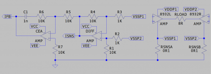
Basically this. The input caps to the 8932 are the ones that are on the board. There are of course output inductors that I left on the board also but didn't include them in the schematic because I am lazy 🙂What was the circuit you tried that didn't work?
And technically instead of adding C1 one could increase the capacitance of the cap in parallel with the speaker but the result is pretty much the same. It reduces the output impedance at high frequencies with a * because my dumb solution rather reduces feedback so the gain is increased at high frequencies which is even worse as a practical circuit but good enough for my experiments since I only wanted to test stability. I did it this way because adding C1 was more reachable when experimenting and since it used bigger cap values which have leads so I didn't have to solder anything but could use spring terminal blocks.
Attachments

Last edited:

For a bridge tied load you can conceptually generate the current sense signal as shown in the attachment. You will have to level shift it which might be done with another differential amp or capacitor coupling might suffice..
In terms of stability...
https://www.nxp.com/docs/en/data-sheet/TDA8932B.pdf
The IC operates without feedback. A current loop as shown is first order and inherently stable. To optimise the gain the slope at the output, ISNS, through the input amplifier must not exceed the slope of the oscillator ramp at the input to the Pulse Width Modulator. Unfortunately there does not seem to be any data for that waveform.
Start out by shorting C1 and increase R6 until you see signs of double pulsing, trying to operate above the clock frequency, or instability in general. Back off a bit when it seems happy. Ideally the loop will be crossing over close to FSW/2PI. Calculate a value for C1 based on your selected R6 to place a pole in the loop at half that frequency. remove the short and test again. Increase C1 if it becomes unstable again.
Attachments
Interesting. Thanks for posting that. I hadn't thought of increasing the sense resistor as increasing the output impedance before, simply as changing the gain, but the two are closely linked--thanks for the insight.Basically this. The input caps to the 8932 are the ones that are on the board. There are of course output inductors that I left on the board also but didn't include them in the schematic because I am lazy 🙂
And technically instead of adding C1 one could increase the capacitance of the cap in parallel with the speaker but the result is pretty much the same. It reduces the output impedance at high frequencies with a * because my dumb solution rather reduces feedback so the gain is increased at high frequencies which is even worse as a practical circuit but good enough for my experiments since I only wanted to test stability. I did it this way because adding C1 was more reachable when experimenting and since it used bigger cap values which have leads so I didn't have to solder anything but could use spring terminal blocks.
Yup, the voltage across the sense resistor is the feedback signal so the larger it is the more current feedback is used and higher output impedance.Interesting. Thanks for posting that. I hadn't thought of increasing the sense resistor as increasing the output impedance before, simply as changing the gain, but the two are closely linked--thanks for the insight.
Since larger sense resistor wastes power you can instead have smaller resistor but amplify the signal with an opamp or a transformer. If I remember correctly Bruno putzeys converted a UCD400OEM to a current source for subwoofer application and used a hall effect sensor for current sense since it had a resistance in the milliohms.
I think I have the paper on my disk somewhere, I'll look for it when I get home.
The whitepaper PDF is too large to upload to the forum so here is a link: https://rmsacoustics.nl/papers/whitepapervelocityfeedback.pdf
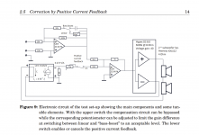
I cut out only the circuit to be more easily viewable from the PDF.
The paper is about using positive current feedback to get a negative impedance amplifier. But the same same circuit should in theory be applicable with flipping the polarity and using negative current feedback to raise output impedance instead. Page 14 has the circuit.
Attachments
Hi!TDA8932 sounds gorgeous when fed with clean power (both power terminals, but most especially pin8)
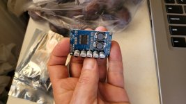
I bought ready 8932 amp in btl mode with single power supply, pict attached.
I mounted it in dead amp and powered with 30,9VDC clean power.
I checked sq without the mods with good DAC and Magnepans 1.6 (83dB of the sensivity, ~3,8 Ohm dc resistance).
I have very mixed impressions, because Maggies are very hard to drive but in general:
- the stereophony is not gorgeous but just accurate,
- the sound is detailed, with many timbres, a little squeaky if too loud,
- the bass is on weaky side,
- middle volume listening is rather fatiguing, possibly 8932 comes to hard clipping (especially in btl mode when driving 3,8 Ohm impedance, look at the datasheet, the amp offers in that case a few watts of the power), tsss and shhh have too much presence, I would call it sharp plasticine, compression occurs,
- low level listening is very pleasant, however without microdetails, with good details on the border of the softness and aggression,
- after burning in the sound softened a bit.
Summary I would comment that 8932 outperforms cheap AB class solid state amplifiers, but really good AB class amps outperforms 8932 regarding the sq.
As I marked, 8932 modules bought by me have cheap parts, I am sure that changing cheap ceramic caps to NP0 (CGO), and general tweaking will help a little but it is rather not for me, too small parts, I use only TH in general.
I will leave the amp for casual listening, and will not experiment with transconductance modes because of smd and a construction od 8932.
But feel free to keep class D transconductance discussion going!
Attachments
Hi Pawel,
Nice work 👍
Datasheet Fig 9 below shows BTL output power for a 4 ohm load.
Clip with a 30V supply will occur at about half the rated input swing.
If you were driving to the full input swing then you must have had significant hard clipping at the peaks.

Did you use a scope to check the output voltage for clipping? Clipping is seen as occasional flat tops with music. Adjust the time base to capture these short peaks.
If you had significant clip then try listening again with the input swing limited to half the rated maximum input swing to prevent clip.
Also with this lowered input swing is the SPL then too weak with Magies for your preferred listening pleasure ?
Nice work 👍
Datasheet Fig 9 below shows BTL output power for a 4 ohm load.
Clip with a 30V supply will occur at about half the rated input swing.
If you were driving to the full input swing then you must have had significant hard clipping at the peaks.
Did you use a scope to check the output voltage for clipping? Clipping is seen as occasional flat tops with music. Adjust the time base to capture these short peaks.
If you had significant clip then try listening again with the input swing limited to half the rated maximum input swing to prevent clip.
Also with this lowered input swing is the SPL then too weak with Magies for your preferred listening pleasure ?
Dear Ian!
thank you for gazing here and a chart, this is what I mentioned in previous post but I thought that I get only a few watts, now I can see I get ~30watts, of course this is not too much for Maggies. What a surprise, I think THD was ~10% and the overall impression was the compression of the sound and presence/unpleasant sibilants. This gives to think what really THD level is acceptable for casual listening... portable speakers have 10% THD too and people use them widely without the complains!
I don't have the scope which would useful for setting safe volume level.
I am happy with low level sound, the amplifier has been burnt in a little and gives a good work when listening the pod-casts or yt. This is impressive: 2X30W amp costs ~10$ and don't demand the cooling radiator!
I am looking forward to buy PCBs of your AB notswitching amp which will surely outperform Pioneer A-88X!
After 3 days of light playing one channel dead!😢
It consumes 54.4mA at the idle, is hot but silent dead.
It consumes 54.4mA at the idle, is hot but silent dead.
I replaced broken module,
now I powered the amps with stabilised 26VDC,
low level sound is excellent again.
I started to think to make new amp using 8932 chip and TH good quality parts (and right output coil for 4 Ohm load).
now I powered the amps with stabilised 26VDC,
low level sound is excellent again.
I started to think to make new amp using 8932 chip and TH good quality parts (and right output coil for 4 Ohm load).
- Home
- Amplifiers
- Class D
- is there class D chip which could work in transconductance mode?, please advice