Steve Eddy said:Oh, by the way, the question isn't simply how much feedback is employed in the CFP, but relative to the Darlington.
Okay, but I'm assuming that by the "loop gain" of the darlington, you mean gm1 * (beta2 + 1) RL, that is, the loop gain of only the first stage? 'Cause that's the only loop that I can conceive of with of the darlington. At any rate, that will need to be computed manually (no problem, since we have the formula above already, assuming you agree with it). The Middlebrook stuff with SPICE assumes there's a physical interconnection you can identify as the loop. There's an identifiable loop with a simple EF, but only if you tap inside the linearized hybrid pi model, which on my freeware simulator isn't directly accessible. (The parameter values are accessible, but you'd have to construct the model yourself from controlled sources). With the CFP I can use subcircuit replication with the full-up Middlebrook techniquie.
As I'm writing this I'm starting to realize what you were trying to say with your earlier post. It seems like the first stage of the darlington will have much lower distortion than the second because of the (beta2 + 1) multiplier of its loop gain. But you end up cascading it with a normal EF, so it would appear that any potential distortion reduction from the increased loop gain of the first stage would be lost with the cascade. Anyway, I'm going to sign off...
Hi Bernhard,
Only that it neither waits nor comes to late.
You are essentially falling in the trap of Zeno's paradox with this argument: http://www.mathacademy.com/pr/prime/articles/zeno_tort/index.asp
Due to the finite slew rate of the signals, the properly designed feedback loop can always subtract the right amount, minus the loopdelay*openloopgain*inputslewrate, which is a small number. In fact, as open loop gain falls with 6dB/oct it works like an integrator, and so its even easier to see that the feedback loop has "enough" time to correct.
Regards,
Peter Jacobi
Bernhard said:Also feedback is mostly a closed loop, the input watches the output and as it finds that the output is mistaken, it tries to correct and "waits" for the results and tries to correct again, but then if the bandwith is too small, the input signal has already changed before the output-watch-circuit has been successful.
Only that it neither waits nor comes to late.
You are essentially falling in the trap of Zeno's paradox with this argument: http://www.mathacademy.com/pr/prime/articles/zeno_tort/index.asp
Due to the finite slew rate of the signals, the properly designed feedback loop can always subtract the right amount, minus the loopdelay*openloopgain*inputslewrate, which is a small number. In fact, as open loop gain falls with 6dB/oct it works like an integrator, and so its even easier to see that the feedback loop has "enough" time to correct.
Regards,
Peter Jacobi
Hi Steven,
thank you very much for the links.
I admit that it's a bit off-topic here, sorry for that. I posted something in the thread "My very first Class D pwm (switching) amplifier."
Maybe I should start a new thread, and in any case I won't post any more details on this here. For updates see here:
http://www.diyaudio.com/forums/showthread.php?s=&postid=333048#post333048
cheers,
Felix
thank you very much for the links.
Steven said:
Maybe it is a good idea to show us your BCA amplifier. I think it deserves a separate thread. At least I'm curious to how you did it, and in general to the pros and cons of balanced current amplification.
Steven
I admit that it's a bit off-topic here, sorry for that. I posted something in the thread "My very first Class D pwm (switching) amplifier."
Maybe I should start a new thread, and in any case I won't post any more details on this here. For updates see here:
http://www.diyaudio.com/forums/showthread.php?s=&postid=333048#post333048
cheers,
Felix
How do you define feedback?
A bipolar EF no more has feedback than a resistor has feedback. The formulas are similar - Io = (Vin-Vout)*gm, Ie=(Vb-Ve)*gm + Ib.
With a darlington or CFP you are just boosting the gm by adding a current gain stage.
I think it depends upon how you define feedback. Normally it requires an addition/subtraction of an input signal to an output signal whose result is fed to the input of the device.
The EF's input is, by definition, a differential - so it should not be confused with a feedback summing point. Otherwise all components become feedback systems, including a single resistor.
I know wy my amp was bad
Hi.... every body..
After some experiment, I know why my amp had bad peformance..it caused of the amp output impedance not low enough to drive speaker amp at high frequency...My amp just use a mosfet driven directly form the driver stage... after I placed additional current booster before the mosfet gate, my amp is getting faster (about 500 kHz), the bass is well controlled now and the distortion is reduced... if some body interst to my schematic, please send me an email..
To Steven,,
you give me good inspiration about your linearized output stage, but I still don't know how its work, would you like to explain it to me??Thxxx alot...
cheers,,
Lukio
Lukio,
Steven did place here the link to Malcolm Hawksford's paper, be so kind and read it. It is Hawksford's output stage.
Steven did place here the link to Malcolm Hawksford's paper, be so kind and read it. It is Hawksford's output stage.
Right, it is http://wes.feec.vutbr.cz/~gratz/Download/Hawksford.ZIP
For the output stage, you only have to look at the pages 1, 2 and 3 (hawksford1, 2, 3). The other pages are about error correction in a.o. gain cells.
Steven
For the output stage, you only have to look at the pages 1, 2 and 3 (hawksford1, 2, 3). The other pages are about error correction in a.o. gain cells.
Steven
Thx for your information....
Hi PMA, Hi Steven..
Thx alot for your information... I've downloaded it but not clear viewed, I' ll try to edit the file...
cheers,
Lukio..
Hi PMA, Hi Steven..
Thx alot for your information... I've downloaded it but not clear viewed, I' ll try to edit the file...
cheers,
Lukio..
I've built one and it sounds like poop on a stick. There's no real way to get around not using feedback with low frequency drivers, or else expect peaky response and poor current drive.
Solid Snake said:I've built one and it sounds like poop on a stick. There's no real way to get around not using feedback with low frequency drivers, or else expect peaky response and poor current drive.
Hmmm, that's funny. I didn't have those kinds of troubles.
Charles Hansen
Charles Hansen said:
Hmmm, that's funny. I didn't have those kinds of troubles.
Charles Hansen
that's the problem with experience: it differes from person to person. One good experience doesn't mean it is a good design, and one bad experience doesn't mean it is a bad design.
Just one more data point.
My "data point".......
Uses Magnepan speakers. No peaking. Lack of current drive not a major issue.
Jocko
Uses Magnepan speakers. No peaking. Lack of current drive not a major issue.
Jocko
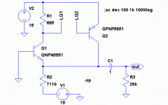
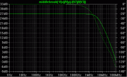
Per the discussion between SE and myself last night, I've looked at the loop gain of a small-signal CFP using the Middlebrook technique. The numbers for this circuit are quite a bit lower than I expected: 27 dB at low frequencies. I have no doubt that a bunch of people will jump in and say "this is totally wrong" 🙂
I've made two identical transistor models, QNPN5551 and QPNP5551, which are NPN and PNP with identical parameters taken from the Fairchild 2N5551. The schematic is shown below, with the loop broken at LG1 and LG2. This is just a small-signal follower, with both transistors biased at 1 mA for simplicity, and hopefully, ease of comparison with the EF. The AC beta for each transistor at the operating point is 140.
I've made two identical transistor models, QNPN5551 and QPNP5551, which are NPN and PNP with identical parameters taken from the Fairchild 2N5551. The schematic is shown below, with the loop broken at LG1 and LG2. This is just a small-signal follower, with both transistors biased at 1 mA for simplicity, and hopefully, ease of comparison with the EF. The AC beta for each transistor at the operating point is 140.
Attachments
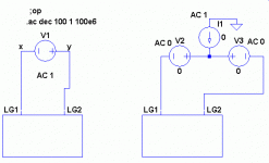
This circuit is replicated as a subcircuit in order to use the "full up" Middlebrook technique, as described in the LoopGain.asc example of LTSpice. That example draws the circuit twice, but I'm using subcircuit replication here. I've used a similar technique analyzing the loop gain of the "super reg" topology, and also my power amp design. I ended up just copying and modifying some of those files. The replicated subcircuits are shown below, where you can see that LG1 and LG2 are connected together outside by the AC voltage sources.
Attachments
The results are shown in the plot below. The function called "middlebrook" is a plotting function which is put into the plot.defs file and looks like:
.func middlebrook(x,y) = (x*y-1)/(x+y+2)
Notice that the loop gain is much lower than expected. You expected beta squared, right? Nope, it's about Rc/re, since when you "unwrap" the loop, you get a cascode.
.func middlebrook(x,y) = (x*y-1)/(x+y+2)
Notice that the loop gain is much lower than expected. You expected beta squared, right? Nope, it's about Rc/re, since when you "unwrap" the loop, you get a cascode.
Attachments
Thanks, Andy!
Not much else to say at this point. I'll await the comarative results for the Darlington.
se
Not much else to say at this point. I'll await the comarative results for the Darlington.
se
That's what I'm trying to figure out at the moment. In between emitter and constant current source load of the first stage maybe? I'm assuming by "loop gain" he means the loop gain of just the first stage. Steve, is that what you mean?
Charles Hansen said:And just how do you think someone is going to "open the loop" of the Darlington?
Dunno. How does the Darlington come to have increased linearity over a single device follower? Gotta be some sort of "open loop gain" or its equivalent in order increase the feedback factor and subsequently linearity, no?
se
- Status
- Not open for further replies.
- Home
- Amplifiers
- Solid State
- Is there anybody built a non feedback amplifier??


