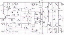
There is my attempt to construct a ‘global feedbackless’ amplifier. On the base of PSpice simulations it should work.
I would like you to express your opinion if it worth further work? Are pots in current sources of differential pairs enough to stabilise zero DC on the output or servo is necessary?
Are bias transistors (from Hawskford correction) should be on the heatsink with output transistors?
Your help is really appreciated.
Attachments
Wow! That's pretty intimidating...
A small advice: you need only one pot for the DC balance, either R6 or R39, but not both.
As for the servo, that will automatically compensate for drift and temp effects. I wonder what the drift of the offset over time will be with the pot, especially since the output stage is not in the feedback loop. Could you accept global DC feedback only, no AC global feedback?
Jan Didden
So do I...I wonder what the drift of the offset over time will be with the pot, especially since the output stage is not in the feedback loop
What do you exactly mean?Could you accept global DC feedback only, no AC global feedback?
Regards
Hi Jarek,
Nice try! It has a lot of similarities with my amp in post #33, but without the emitter follower to get a lower impedance for the Hawksford stage and you have applied multi-stage feedback (although not from the output). And this latter complicates things a lot.
Now you have created two interacting feedback loops, one error feedback loop (the Hawksford stage, Q10, Q11), and one negative feedback loop that is connected from a node within the error feedback loop (R11, R34, R19) to the input differentials. I'm still puzzled whether that really works. Changes in the load current of the output stage will cause output voltage changes, that will be compensated for by the error feedback stage. In that process the emitter voltages of Q1, Q17 will change, but still these voltages are used by the normal feedback loop via R11 and R34. I think I would prefer the output of the amplifier as feedback node if you want to use feedback (but then it is no global feedback free amplifier anymore). Or change your input stage and VAS so that it can work as overall feedback free amplifier.
The ratio of the collector vs emitter resistors of the error correction amplifier is very high (R13, 33 vs R11, R34) and not satisfying the zero error condition. But maybe the impedance of R13 and R33 is lowered by the act of the negative feedback loop to make it right again, but then probably it is not very stable with frequency and output voltage.
Yes, you need to put the bias/error transistors Q10, Q11 on the heatsink for proper temperature tracking.
Steven
jarek said:
So do I...
What do you exactly mean?
Regards
You could use a servo circuit that takes the output voltage, removes the AC component (usually it is an integrator) so that only the DC offset remains at the servo output. This is then fed back to the input stage to null the output offset. So, it is global feedback, but only for DC. In reality, it is feedback for very low AC freq and DC, depending on the integrator time constant. Usually a break freq of a few Hz is used. There are many examples of servo's on the net, also on this forum.
You should also closely look at Steven's comments above. The interaction of the feedback loops looks not kosher indeed. The Hawksford correction relies on a very precise 1:1 returning of the output voltage error to the input of the output stage. The Essex university has all of Hawksford papers on-line, including this error correction article.
Jan Didden
Jarek,
Use a filter at the input, so that high frequency signals can’t reach the input transistors.
Because you don't use a capacitor in the feedback loop (that is oké), any offset voltage on the input will be multiplied by 22x. If the temp drift of D1 and D2 will differ, I think there will be an offset voltage at the output after some time.
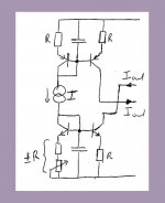
I suggest to connect the bases of Q3 and Q15 by a current source. To cancel the temp drift of the Vbe, use a current mirror. For the best result, make the Vbe of the transistors equal to each other by using the same emittor resistors R. In that case Iout will be almost equal to I. See the attachment.
If you use stabilised supplies, you can use a resistor instead of a current source.
Marc
Use a filter at the input, so that high frequency signals can’t reach the input transistors.
Because you don't use a capacitor in the feedback loop (that is oké), any offset voltage on the input will be multiplied by 22x. If the temp drift of D1 and D2 will differ, I think there will be an offset voltage at the output after some time.
I suggest to connect the bases of Q3 and Q15 by a current source. To cancel the temp drift of the Vbe, use a current mirror. For the best result, make the Vbe of the transistors equal to each other by using the same emittor resistors R. In that case Iout will be almost equal to I. See the attachment.
If you use stabilised supplies, you can use a resistor instead of a current source.
Marc
Attachments
Thanks Jan and Steven for your comments.
Yes Steven, it was your design which impressed me a lot to this work 🙂
I was looking for solution to avoid rebuilding VAS stage and adding one more stage with emitter follower and tried that ‘overlapping’ feedback connection. According to spice simulations this work and there is no problem with stability. The gain in open loop is rather low (~ 400), gain bandwidth about 5 – 6 MHz and phase margin about 70-80 deg. But it is only simulations.. and I do not trust them much.
My fears are the same, but in simulations....maybe I should try and verify it in real world?
Sorry Jan, I thought you had something special here. A thanks for advises.
Regards
Yes Steven, it was your design which impressed me a lot to this work 🙂
Now you have created two interacting feedback loops, one error feedback loop (the Hawksford stage, Q10, Q11), and one negative feedback loop that is connected from a node within the error feedback loop (R11, R34, R19) to the input differentials. I'm still puzzled whether that really works
I was looking for solution to avoid rebuilding VAS stage and adding one more stage with emitter follower and tried that ‘overlapping’ feedback connection. According to spice simulations this work and there is no problem with stability. The gain in open loop is rather low (~ 400), gain bandwidth about 5 – 6 MHz and phase margin about 70-80 deg. But it is only simulations.. and I do not trust them much.
The ratio of the collector vs emitter resistors of the error correction amplifier is very high (R13, 33 vs R11, R34) and not satisfying the zero error condition. But maybe the impedance of R13 and R33 is lowered by the act of the negative feedback loop to make it right again, but then probably it is not very stable with frequency and output voltage.
My fears are the same, but in simulations....maybe I should try and verify it in real world?
You could use a servo circuit that takes the output voltage, removes the AC component (usually it is an integrator) so that only the DC offset remains at the servo output
Sorry Jan, I thought you had something special here. A thanks for advises.
Regards
Hi Marc.
What do yoy think about using led's to compensate DC drift?
Thanks for the schematic.
regards
I suggest to connect the bases of Q3 and Q15 by a current source
What do yoy think about using led's to compensate DC drift?
Thanks for the schematic.
regards
jarek said:
My fears are the same, but in simulations....maybe I should try and verify it in real world?
Jarek, did you try to simulate the amplifier with and without load, or even better a modulated load? You could try to use an 8 Ohm resistor load with the other end not connected to ground but to a square wave oscillator. Then check the feedthrough to the output of the amplifier. Error correction is optimal for minimum feedthrough. But try this for different frequencies and check whether the error correction performance is sufficient for all frequencies of interest.
Maybe Jan had more in mind initially, than appeared from his answer about servos. If you change R25 to a (big) capacitor you will get DC feedback without AC feedback, at least for higher frequencies. DC gain is one in that case, so offset becomes small. In your case the AC gain will be too high (you wrote 400x), but that can be lowered by increasing R15, 16, 31, 32 and decreasing R13, 33. Or just insert a capacitor in series with R25 and you get the standard feedback circuit, found in almost all amplifiers with the required AC gain and a DC gain of one.jarek said:
Sorry Jan, I thought you had something special here. A thanks for advises.
I don't think two LEDs have much better temperature tracking than two zener diodes or two transistors. Ok, maybe some. It depends on the forward voltage related to the temperature drift. A larger voltage for the same drift in mV/*C is better, like using 5V6 zeners which have a tempco of about zero. But zeners are more noisy, so you might need more filtering here. Furthermore, it is not only the drift of the current sources that affects the DC offset. Also the drift of the input pairs and the drift of Q2, 4, 20, 16 play an important role.jarek said:
What do yoy think about using led's to compensate DC drift?
Steven
I did my simulations with 4-ohm load, but only with reference to THD distortions for 1kHZ and 20 kHz. I checked it with or without Hawskford correction. I noticed a pretty improvement in these figures. I also tried to tune the correction with R11, RR34 and R20 and it worked. I will try your suggestion with square wave oscillator.did you try to simulate the amplifier with and without load, or even better a modulated load?
It would be a nice way if the drift were too much. But what say audiophiles than? 😉If you change R25 to a (big) capacitor you will get DC feedback without AC feedback, at least for higher frequencies. DC gain is one in that case, so offset becomes small. In your case the AC gain will be too high (you wrote 400x), but that can be lowered by increasing R15, 16, 31, 32 and decreasing R13, 33. Or just insert a capacitor in series with R25
Thanks, Steven, for your interest.

Ok!nember one!A small advice: you need only one pot for the DC balance, either R6 or R39, but not both
If you use a small power variable resistor ,it will fail about 3-4 month.
Hi Jarek,
Sorry for my late reply. The error correction seems to work indeed. Congrats. Still I think you better connect the feedback network to the amp output.
Your last picture shows a less effective error correction. I think the collector impedance seen at the output of the VAS stage (and the output of the error correction amp) is not very constant(without feedback, with these high values of resistors R13, 33, with Miller C's) across the whole frequency range. Therefor the balance condition of the error amplifier drifts.
Maybe you should adjust R13, 33 and not R11, 34.
Steven
thanh
I don't know a THD figures of this amp in reality. All here are only simulations in PSpice.
Steven
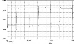
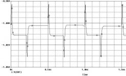
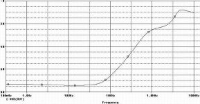
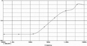
Here two simulation, one with feedback from VAS stage and the second with feedback from the output of the amplifier. I was trying to correct resistance of R11 and R34 to obtain minimum voltage at the output. A modulated voltage source was connected to 4 ohm load and the ground. Y-axis is in dB.
Changing resistance of R13 and R33 do not gives as good result. I think, dumping factor depends on error correction and a gain of the VAS. The sum of both gives a result. When we lower resistance R13 and R33 than we get less gain and therefore summarised effect is worse.
With feedback from VAS stage:
I don't know a THD figures of this amp in reality. All here are only simulations in PSpice.
Steven
Here two simulation, one with feedback from VAS stage and the second with feedback from the output of the amplifier. I was trying to correct resistance of R11 and R34 to obtain minimum voltage at the output. A modulated voltage source was connected to 4 ohm load and the ground. Y-axis is in dB.
Changing resistance of R13 and R33 do not gives as good result. I think, dumping factor depends on error correction and a gain of the VAS. The sum of both gives a result. When we lower resistance R13 and R33 than we get less gain and therefore summarised effect is worse.
With feedback from VAS stage:
Attachments
Thanks Jarek,
The differences are not too big between both methods (once it is clear that the scale is different). For low frequencies the circuit with output feedback is a little better for THD, above 1kHz the version with feedback from the driver is a little better for THD.
Steven
The differences are not too big between both methods (once it is clear that the scale is different). For low frequencies the circuit with output feedback is a little better for THD, above 1kHz the version with feedback from the driver is a little better for THD.
Steven
- Status
- Not open for further replies.
- Home
- Amplifiers
- Solid State
- Is there anybody built a non feedback amplifier??