Then either you are measuring it incorrectly or your meter is shot, is there a fuse in your meter? Does it measure Ohms or DC Volts?
Craig
Craig
It probably isn't shot. But the amp may not be turning on since it works well with speakers.
I probably should measure the current into the speaker via an amp clamp (which I dont have).
Thanks.
Srinath.
I probably should measure the current into the speaker via an amp clamp (which I dont have).
Thanks.
Srinath.
Measure with the speakers connected.
200mV into those RCA jacks in the back of your amp will produce 4V RMS at the speaker out terminals and into the speakers themselves, a quite annoying level at 1 kHz.
.2V out will sound like there's a bee in the room or a cheap pocket radio.
0V out will sound like .... well .... imagine it 😉
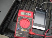
Please post a picture showing your meter on a table, attached to your power amp out by it, so we see your actual connections, the scale you set it to, what it displays and its brand and model, so we run away when we see one on sale 😉
Why you think you need a current clamp is beyond me.
Unless it's a made up excuse not to measure.
200mV into those RCA jacks in the back of your amp will produce 4V RMS at the speaker out terminals and into the speakers themselves, a quite annoying level at 1 kHz.
.2V out will sound like there's a bee in the room or a cheap pocket radio.
0V out will sound like .... well .... imagine it 😉
Please post a picture showing your meter on a table, attached to your power amp out by it, so we see your actual connections, the scale you set it to, what it displays and its brand and model, so we run away when we see one on sale 😉
Why you think you need a current clamp is beyond me.
Unless it's a made up excuse not to measure.
The amp clamp can meaure the current running into 1 speaker - I suspect the amp isn't turning on with the DMM but it is turning on with speakers.
Why would I not want to do stuff you guys suggest, you're trying to help me fix it. So I'll do it. Except if I had to buy some crazy stuff I cant afford or find ...
Cool.
Srinath.
Why would I not want to do stuff you guys suggest, you're trying to help me fix it. So I'll do it. Except if I had to buy some crazy stuff I cant afford or find ...
Cool.
Srinath.
Pics here
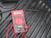
Pics of testing and my wonderful cen-tech meter.
And in the AC test mode without anything connectd the meter just flips between -0.00 and 0.00. So I guess it was just 0 when left was connected.
The first pic is the meter connected to the extension cord. Just to show it works.
Thanks.
Srinath.
Pics of testing and my wonderful cen-tech meter.
And in the AC test mode without anything connectd the meter just flips between -0.00 and 0.00. So I guess it was just 0 when left was connected.
The first pic is the meter connected to the extension cord. Just to show it works.
Thanks.
Srinath.
Attachments
Last edited:
Y
Sorry for the French but nonsense.
a) encapsulation plastic is Epoxy, a very good one by the way, which is not thermoplastic so it will decompose and crack rather than melt.
And its temperature limit is way higher than 200C anyway.
Just melt a drop of solder which is much hotter and apply it to the top of any power transistor, leaving the soldering iron tip in contact with it to keep temperature very high.
b) What gets destroyed above 150/175/200C is the actual atom lattice/structure inside the chip crystal which makes it a transistor or whatever instead of a plain piece of metal.
The chip inside dies above 150/175/200C , way below any casing material does.
No, the glass transition point of some "plastic" packages is only 150C or lower. The chips can work fine even at 210C (see recent parts for down hole instrumentation, cerdip only). There also are lots of parts rated at 150C case temperature where the die is much higher.
EDIT - A sample fair use quote, I'm afraid the complete IEEE articles are pay only.
"Compounds have made enormous improvements in reliability behavior over the years, under both moist and dry conditions, but still have some inherent shortcomings. For one, epoxy molding compounds are required to meet the Underwriter's Laboratories Flammability Rating of 94V-0. To meet that rating, bromine and antimony are often incorporated as flame retardants. Unfortunately, these elements can act as catalysts to accelerate the intcrmetalllic growth between the gold ball bond and the aluminium bond pad on the silicon chip. The intermetallic growth itself is not detrimental, but the secondary effects of Kirkendall voiding and thermal stresses between the interrnetallic layers are. This phenomenon is typically seen during high temperature storage life reliability testing. Also, many epoxy cresol novalac-based compounds have glass transition temperatures of around 150ïC, but the biphenyl-based compounds recently introduced may range as low as 120C."
Last edited:
I've repaired a few Carver amps with the the Magnetic Field power supply and I don't remember having any trouble running them without a load. As with any solid state amplifier I always first test it without a load, only after it checks out then it gets connected to a dummy load. The only thing I can think of is DC offset that is being killed with a load attached. There is no reason a properly functioning amplifier shouldn't pass a signal without a load. The service manual explains all of the fault conditions for protect mode. I know you say it's not in protect but that's the only explanation. Try measuring for DC offset without a load just to be sure.
Craig
Craig
This is an M200t. It sounds pretty good and clean, and you'd never know somehitng was wrong with it if it was run with the preamp @ 10 oclock.
I actually have a pioneer sa7100 (I think) that's about the same way, 10 oclock on the balance and its great.
I am thinking I'll let it go till I get smarter (which may not happen for a long time)
Otherwiise I think it could be the zobel in the rear output panel.
I'll pull it and test it and see. Lets see what it does.
Cool.
Srinath.
An AC voltmeter that has two scales of 750Vac and 200Vac is almost useless for DIYaudio.
Get one that has full scale reading down to 200.0mVac
They are available cheap !
I bought some for my school that cost ~£3 (~$5usd) and accuracy was pretty good. Better than an analogue meter.
Get one that has full scale reading down to 200.0mVac
They are available cheap !
I bought some for my school that cost ~£3 (~$5usd) and accuracy was pretty good. Better than an analogue meter.
Yea I am realizing that.
However - why am I getting .2 v ac out of speaker terminals ? A better meter wont get me more voltage.
Cool.
Srinath.
However - why am I getting .2 v ac out of speaker terminals ? A better meter wont get me more voltage.
Cool.
Srinath.
I used to have a self ranging DMM (was bloody $$$ too) and I used to hate it. Way back when I was trying to fix my TV it was really annoying IMHO. However I had a question about auto ranging meters.
When the meter is in the volt mode it has several 1000 - million ohm internal resistance right ?
If it sees very low voltage, does it lower than value, like you start measuring, and it starts @ 1 mega ohm, but it sees under 1v, so does it drop the internal resistance to say 100 ohm and then the voltage creeps up to 1.1v, and it stops there ?
And if the meters range was manually adjusted, does it have lower internal resistance at lower range of measurement. So you first start measuring at the highest voltage, then lower it progressively when you are measuring an unknown voltage. I do that with DC mode in this meter.
Thanks.
Srinath.
My meters behave differently.
The bench top and a recent cheap hand held have a near constant 10M input impedance in both AC and DC voltmeter mode.
A very old meter has 10M for all the scales above 2.000Vac.
200.mVac is only 293k and 2.000Vac is 1M
The bench top and a recent cheap hand held have a near constant 10M input impedance in both AC and DC voltmeter mode.
A very old meter has 10M for all the scales above 2.000Vac.
200.mVac is only 293k and 2.000Vac is 1M
That's the point.
Even a cheap meter can and will read 4V AC/RMS ..... unless there is no AC/Audio there.
But then the amp is mute.
It might be something as stupid as a poorly made interconnecting cable, your phone not sending audio, etc.
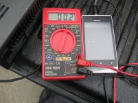
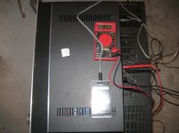
I see no speakers are connected , so you can't be really certain that the tone is actually being played.
Now I'm satisfied that the multimeter is set properly , but don't see how it's connected to the amp, in fact the red probe is NOT connected to the red speaker out, only the black one is .
Probes are not magical, they must actually touch what they want to measure, otherwise they display "0" or, best case, add a flipping "-" sign in front, which shows the meter is hunting around "0", while yours ..... hey !!! ..... wait !!!!
I'm boring of this game of not_actually_answering so for the last time (do it all or don't bother posting):
1) connect both speakers
2) play the 1 kHz tone into the amplifier (turn it on first)
3) you hear a quite loud annoying 1kHz tone through both speakers (Y/N)
If NO, recheck all connections until you do.
If you still don't hear it, forget the test and go doing something else.
If YES:measure AC voltage, 200VAC scale, red and black probes to red and black terminals on one channel (do not disconnect the speakers to be certain that the tone is still present), then on the other.
Post what you read for each channel. Label that Test 1
4) interchange the RCA connectors (right to left and viceversa) and repeat measurements. You must still hear the 1 kHz tone through both speakers.
Post what you read for each channel. Label that Test 2
5) post all 4 results (2 right, 2 left) here.
Even a cheap meter can and will read 4V AC/RMS ..... unless there is no AC/Audio there.
But then the amp is mute.
It might be something as stupid as a poorly made interconnecting cable, your phone not sending audio, etc.
I see no speakers are connected , so you can't be really certain that the tone is actually being played.
Now I'm satisfied that the multimeter is set properly , but don't see how it's connected to the amp, in fact the red probe is NOT connected to the red speaker out, only the black one is .
Probes are not magical, they must actually touch what they want to measure, otherwise they display "0" or, best case, add a flipping "-" sign in front, which shows the meter is hunting around "0", while yours ..... hey !!! ..... wait !!!!
I'm boring of this game of not_actually_answering so for the last time (do it all or don't bother posting):
1) connect both speakers
2) play the 1 kHz tone into the amplifier (turn it on first)
3) you hear a quite loud annoying 1kHz tone through both speakers (Y/N)
If NO, recheck all connections until you do.
If you still don't hear it, forget the test and go doing something else.
If YES:measure AC voltage, 200VAC scale, red and black probes to red and black terminals on one channel (do not disconnect the speakers to be certain that the tone is still present), then on the other.
Post what you read for each channel. Label that Test 1
4) interchange the RCA connectors (right to left and viceversa) and repeat measurements. You must still hear the 1 kHz tone through both speakers.
Post what you read for each channel. Label that Test 2
5) post all 4 results (2 right, 2 left) here.
I hear the tone quite a bit. @ 1k hz the left is very much weaker, but @ 250 or 440 the difference is a bit less pronounced.
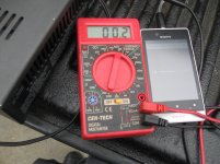
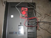
I'll show you the connection in pics next, but trust me, its in there and clipped in. You dont think I got .2v without touching the probes do you. Its not just touching, its clipped in the spring loaded clips.
Cool.
Srinath.
I'll show you the connection in pics next, but trust me, its in there and clipped in. You dont think I got .2v without touching the probes do you. Its not just touching, its clipped in the spring loaded clips.
Cool.
Srinath.
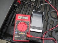
.2 v AC in the louder channel.
0 v ac in the weaker channel.
That is with the speakers connected and playing 440 hz. I have video clips as well, dont know how to put it up.
Cool.
Srinath.
0 v ac in the weaker channel.
That is with the speakers connected and playing 440 hz. I have video clips as well, dont know how to put it up.
Cool.
Srinath.
That is 4 results, two from Test 1 and two from Test 2.1) connect both speakers
2) play the 1 kHz tone into the amplifier (turn it on first)
3) you hear a quite loud annoying 1kHz tone through both speakers (Y/N)...............
............Post what you read for each channel. Label that Test 1
4) interchange the RCA connectors (right to left and viceversa) and repeat measurements. ....... Label that Test 2
5) post all 4 results (2 right, 2 left) here.
Report Post ........
If you want to repeat at a different frequency, then that is 4 more results.
That was exactly what I did, I have video of it too. That is what the pics are too.
1khz I didn't use that, the 440hz made the most sense, it was where I heard the least difference between left and right. 1khz was about the same, I heard a much bigger difference with 1k.
Thanks.
Srinath.
1khz I didn't use that, the 440hz made the most sense, it was where I heard the least difference between left and right. 1khz was about the same, I heard a much bigger difference with 1k.
Thanks.
Srinath.
- Status
- Not open for further replies.
- Home
- Amplifiers
- Solid State
- Is there a better transistor than a Motorola C4000/C5000